TOUCH SELECT 2-4 AND HIGH-LOW SYSTEM Shift Motor Circuit
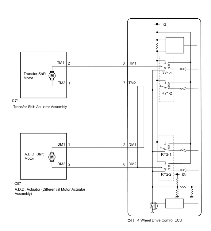
WIRING DIAGRAM
CAUTION / NOTICE / HINT
Note
When the vehicle is stopped, mode switching may be unavailable depending on the phase of the transfer assembly and A.D.D. actuator powertrain. There is no malfunction if mode switching is available after the vehicle is moved.
PROCEDURE
-
CONFIRM PROBLEM SYMPTOM
-
Confirm the problem symptoms.
Result Result Proceed to The 4WD indicator light (green) is blinking* A The 4LO indicator light is blinking* B
-
*: Blinks at 0.5 second intervals (0.5 seconds on and 0.5 seconds off)
-
B 
GO TO STEP 7 Click here
A 
-
-
CHECK TRANSFER POSITION
-
Lift up the vehicle until all four wheels are off the ground.
-
for Automatic Transmission:
Move the shift lever to N.
for Manual Transmission:
Move the shift lever to neutral.
-
Turn the transfer position switch from H2 to H4.
Tech Tips
The 4WD indicator light (green) continues to blink*.
-
*: Blinks at 0.5 second intervals (0.5 seconds on and 0.5 seconds off)
-
-
Release the parking brake.
-
Turn the ignition switch off.
-
Disconnect the C74 transfer shift actuator assembly connector.
-
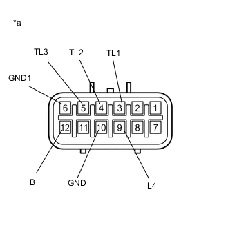
*a Component without harness connected
(Transfer Shift Actuator Assembly)
Measure the resistance according to the value(s) in the table below.
Tech Tips
Check that the terminals of the limit switch, 4WD detection switch and L4 detection switch of the transfer shift actuator assembly (TL1, TL2, TL3, B and L4) are in the condition shown in the table below (H4).
Terminal When H4 TL1 OFF (OPEN) TL2 OFF (OPEN) TL3 ON (GND) B ON (GND) L4 OFF (OPEN) Standard Resistance Tester Connection Condition Specified Condition 3 (TL1) - 6 (GND1) Transfer H4 10 kΩ or higher 4 (TL2) - 6 (GND1) 10 kΩ or higher 5 (TL3) - 6 (GND1) Below 1 Ω 12 (B) - 10 (GND) Below 1 Ω 9 (L4) - 10 (GND) 10 kΩ or higher Result Result Proceed to OK (H4 condition) A NG (not H4 condition) B
B
CHECK TRANSFER SHIFT ACTUATOR ASSEMBLY (TRANSFER SHIFT MOTOR) Click here
A
-
-
CHECK DIFFERENTIAL MOTOR ACTUATOR ASSEMBLY (A.D.D. SHIFT MOTOR)
-
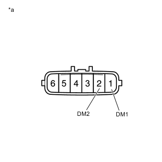
*a Component without harness connected
(A.D.D. Actuator (Differential Motor Actuator Assembly))
Disconnect the C57 A.D.D. actuator (differential motor actuator assembly) connector.
-
Measure the resistance according to the value(s) in the table below.
Standard Resistance Tester Connection Condition Specified Condition 1 (DM1) - 2 (DM2) Always 1.5 to 10 Ω Result Proceed to OK NG
NG 
REPLACE DIFFERENTIAL MOTOR ACTUATOR ASSEMBLY Click here
OK
-
-
CHECK HARNESS AND CONNECTOR (4 WHEEL DRIVE CONTROL ECU - DIFFERENTIAL MOTOR ACTUATOR ASSEMBLY)
-
Disconnect the C61 4 wheel drive control ECU connector.
-
Disconnect the C57 A.D.D. actuator (differential motor actuator assembly) connector.
-
Measure the resistance according to the value(s) in the table below.
Standard Resistance Tester Connection Condition Specified Condition C61-2 (DM1) - C57-1 (DM1) Always Below 1 Ω C61-6 (DM2) - C57-2 (DM2) Always Below 1 Ω C61-2 (DM1) or C57-1 (DM1) - C61-6 (DM2) or C57-2 (DM2) Always 10 kΩ or higher Result Proceed to OK NG
NG
REPAIR OR REPLACE HARNESS OR CONNECTOR
OK
-
-
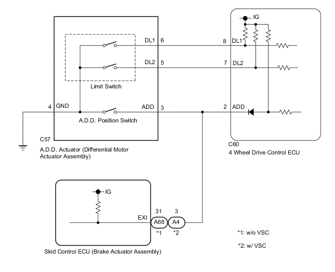
CHECK HARNESS AND CONNECTOR (4 WHEEL DRIVE CONTROL ECU - DIFFERENTIAL MOTOR ACTUATOR ASSEMBLY)
-
Disconnect the C60 4 wheel drive control ECU connector.
-
Disconnect the C57 A.D.D. actuator (differential motor actuator assembly) connector.
-
w/o VSC:
Disconnect the A68 skid control ECU (brake actuator assembly) connector.
w/ VSC:
Disconnect the A4 skid control ECU (brake actuator assembly) connector.
-
Measure the resistance according to the value(s) in the table below.
Standard Resistance Tester Connection Condition Specified Condition C60-8 (DL1) - C57-6 (DL1) Always Below 1 Ω C60-7 (DL2) - C57-5 (DL2) Always Below 1 Ω C60-2 (ADD) - C57-3 (ADD) Always Below 1 Ω C57-4 (GND) - Body ground Always Below 1 Ω C60-8 (DL1) or C57-6 (DL1) - Body ground Always 10 kΩ or higher C60-7 (DL2) or C57-5 (DL2) - Body ground Always 10 kΩ or higher C60-2 (ADD) or C57-3 (ADD) - Body ground Always 10 kΩ or higher Result Proceed to OK NG
NG
REPAIR OR REPLACE HARNESS OR CONNECTOR
OK
-
-
INSPECT DIFFERENTIAL MOTOR ACTUATOR ASSEMBLY (LIMIT SWITCH AND A.D.D. POSITION SWITCH)
-
Turn the ignition switch off.
-
Remove the A.D.D. actuator (differential motor actuator assembly).
-
Check the limit switch and A.D.D. position switch of the A.D.D. actuator (differential motor actuator assembly).
Result Proceed to OK NG
OK
REPLACE 4 WHEEL DRIVE CONTROL ECU Click here
NG
REPLACE DIFFERENTIAL MOTOR ACTUATOR ASSEMBLY Click here
-
-
CHECK TRANSFER SHIFT ACTUATOR ASSEMBLY (TRANSFER SHIFT MOTOR)
-
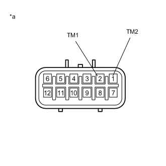
*a Component without harness connected
(Transfer Shift Actuator Assembly)
Disconnect the C74 transfer shift actuator assembly connector.
-
Measure the resistance according to the value(s) in the table below.
Standard Resistance Tester Connection Condition Specified Condition 2 (TM1) - 1 (TM2) Always 1.5 to 10 Ω Result Proceed to OK NG
NG
REPLACE TRANSFER SHIFT ACTUATOR ASSEMBLY Click here
OK
-
-
CHECK HARNESS AND CONNECTOR (4 WHEEL DRIVE CONTROL ECU - TRANSFER SHIFT ACTUATOR ASSEMBLY)
-
Disconnect the C61 4 wheel drive control ECU connector.
-
Disconnect the C74 transfer shift actuator assembly connector.
-
Measure the resistance according to the value(s) in the table below.
Standard Resistance Tester Connection Condition Specified Condition C61-8 (TM1) - C74-2 (TM1) Always Below 1 Ω C61-7 (TM2) - C74- 1 (TM2) Always Below 1 Ω C61-8 (TM1) or C74-2 (TM1) - C61-7 (TM2) or C74-1 (TM2) Always 10 kΩ or higher Result Proceed to OK NG
NG
REPAIR OR REPLACE HARNESS OR CONNECTOR
OK
-
-
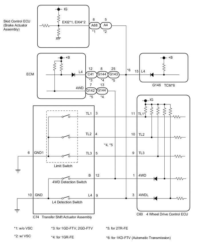
CHECK HARNESS AND CONNECTOR (4 WHEEL DRIVE CONTROL ECU - TRANSFER SHIFT ACTUATOR ASSEMBLY)
-
Disconnect the C60 4 wheel drive control ECU connector.
-
Disconnect the C74 transfer shift actuator assembly connector.
-
w/o VSC:
Disconnect the A68 skid control ECU (brake actuator assembly) connector.
w/ VSC:
Disconnect the A4 skid control ECU (brake actuator assembly) connector.
-
for 1GD-FTV, 2GD-FTV:
Disconnect the C41 ECM connector.
for 1GR-FE:
Disconnect the G144 ECM connector.
for 2TR-FE:
Disconnect the G142 and G143 ECM connectors.
for 1KD-FTV (Automatic Transmission):
Disconnect the G146 TCM connector.
-
Measure the resistance according to the value(s) in the table below.
Standard Resistance Tester Connection Condition Specified Condition C60-11 (TL1) - C74-3 (TL1) Always Below 1 Ω C60-10 (TL2) - C74-4 (TL2) Always Below 1 Ω C60-9 (TL3) - C74-5 (TL3) Always Below 1 Ω C74-6 (GND1) - Body ground Always Below 1 Ω C60-1 (4WD) - C74-12 (B) Always Below 1 Ω C60-3 (4WDL) - C74-9 (L4) Always Below 1 Ω C74-10 (GND) - Body ground Always Below 1 Ω C60-11 (TL1) or C74-3 (TL1) - Body ground Always 10 kΩ or higher C60-10 (TL2) or C74-4 (TL2) - Body ground Always 10 kΩ or higher C60-9 (TL3) or C74-5 (TL3) - Body ground Always 10 kΩ or higher C60-1 (4WD) or C74-12 (B) - Body ground Always 10 kΩ or higher C60-3 (4WDL) or C74-9 (L4) - Body ground Always 10 kΩ or higher Result Proceed to OK NG
NG
REPAIR OR REPLACE HARNESS OR CONNECTOR
OK
-
-
INSPECT TRANSFER SHIFT ACTUATOR ASSEMBLY (LIMIT SWITCH AND 4WD DETECTION SWITCH)
-
Turn the ignition switch off.
-
Remove the transfer shift actuator assembly.
-
Check the limit switch, 4WD detection switch and L4 detection switch of the transfer shift actuator assembly.
Result Proceed to OK NG
OK
REPLACE 4 WHEEL DRIVE CONTROL ECU Click here
NG
REPLACE TRANSFER SHIFT ACTUATOR ASSEMBLY Click here
-