VEHICLE STABILITY CONTROL SYSTEM Downhill Assist Control Indicator Light does not Come ON
DESCRIPTION
Even if the downhill assist control switch is pressed, the downhill assist control indicator light blinks and downhill assist control does not activate under the following conditions:
-
Shift position is P.
-
The 4WD control switch (transfer position switch) set to H2.
-
The rear differential is locked.
-
The vehicle speed is 30 km/h (19 mph) or more.
-
The brake system is malfunctioning.
-
Temperature of the brake actuator assembly increases and the downhill assist control is temporarily canceled.
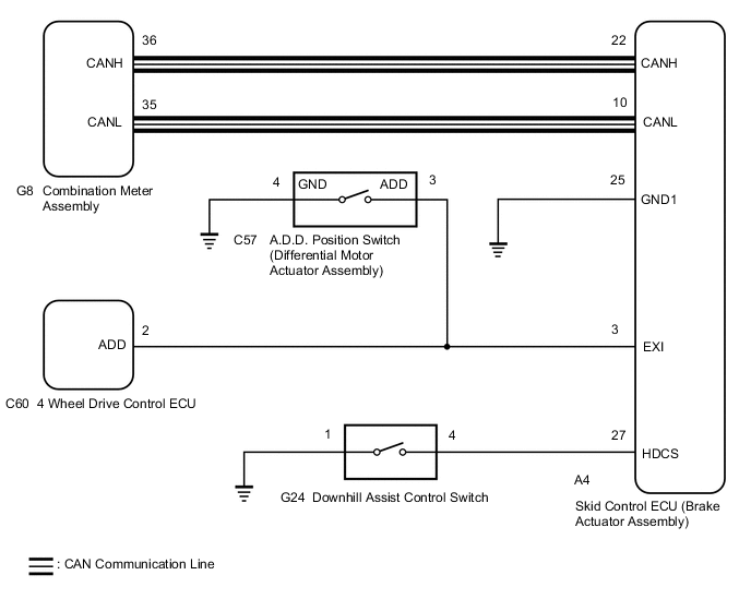
WIRING DIAGRAM
CAUTION / NOTICE / HINT
Note
When replacing the skid control ECU (brake actuator assembly), perform zero point calibration.
PROCEDURE
-
CHECK CAN COMMUNICATION SYSTEM
-
Check if CAN communication system DTCs are output.
Result Proceed to DTC is not output DTC is output
DTC is output 
CHECK CAN COMMUNICATION SYSTEM Click here
DTC is not output 
-
-
CHECK HARNESS AND CONNECTOR (EXI TERMINAL)
-
Turn the ignition switch to ON.
-
Turn the 4WD control switch (transfer position switch) to H4 or L4.
-
Turn the ignition switch off.
-
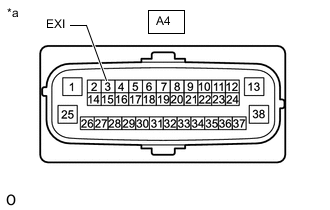
*a Front view of wire harness connector
(to Skid Control ECU [Brake Actuator Assembly])
Disconnect the A4 skid control ECU (brake actuator assembly) connector.
-
Turn the ignition switch to ON.
-
Measure the voltage according to the value(s) in the table below.
Standard Voltage Tester Connection Condition Specified Condition A4-3 (EXI) - Body ground
-
Ignition switch ON
-
4WD control switch (transfer position switch) set to H4 or L4
Below 1.5 V -
-
Turn the ignition switch off.
-
Reconnect the A4 skid control ECU (brake actuator assembly) connector.
-
Turn the ignition switch to ON.
-
Turn the 4WD control switch (transfer position switch) to H2.
-
Turn the ignition switch off.
-
Disconnect the A4 skid control ECU (brake actuator assembly) connector.
-
Turn the ignition switch to ON.
-
Measure the voltage according to the value(s) in the table below.
Standard Voltage Tester Connection Condition Specified Condition A4-3 (EXI) - Body ground
-
Ignition switch ON
-
4WD control switch (transfer position switch) set to H2
11 to 14 V Result Proceed to OK NG -
NG 
CHECK HARNESS AND CONNECTOR (EXI TERMINAL CIRCUIT) Click here
OK
-
-
INSPECT DOWNHILL ASSIST CONTROL SWITCH
-
Turn the ignition switch off.
-
Remove the downhill assist control switch.
-
Inspect the downhill assist control switch.
OK The downhill assist control switch operates normally. Result Result OK NG
NG
REPLACE DOWNHILL ASSIST CONTROL SWITCH Click here
OK
-
-
CHECK HARNESS AND CONNECTOR (BRAKE ACTUATOR ASSEMBLY - DOWNHILL ASSIST CONTROL SWITCH)
-
Measure the resistance according to the value(s) in the table below.
Standard Resistance Tester Connection Condition Specified Condition A4-27 (HDCS) - G24-4 Always Below 1 Ω A4-27 (HDCS) or G24-4 - Body ground Always 10 kΩ or higher G24-1 - Body ground Always Below 1 Ω Result Result OK NG
NG
REPAIR OR REPLACE HARNESS OR CONNECTOR
OK
-
-
PERFORM ACTIVE TEST USING GTS (DOWNHILL ASSIST CONTROL LIGHT)
-
Reconnect the A4 skid control ECU (brake actuator assembly) connector.
-
Reconnect the G24 downhill assist control switch connector.
-
Connect the GTS to the DLC3.
-
Turn the ignition switch to ON.
-
Turn the GTS on.
-
Enter the following menus: Chassis / ABS/VSC/TRC / Data List.
-
According to the display on the GTS, perform the Active Test.
Chassis > ABS/VSC/TRC > Active TestTester Display Measurement Item Control Range Diagnostic Note Downhill Assist Control Light Downhill assist control indicator light Indicator light ON/OFF Observe combination meter assembly
Vehicle condition: Vehicle stopped
-
When performing the ABS Warning Light Active Test, check Downhill assist control indicator light in the Data List.
Chassis > ABS/VSC/TRC > Data ListTester Display Measurement Item Range Normal Condition Diagnostic Note Downhill Assist Control Light Downhill assist control indicator light ON or OFF OFF: Downhill assist control indicator light off
ON: Downhill assist control indicator light on
-
Chassis > ABS/VSC/TRC > Active TestActive Test Display Downhill Assist Control Light Data List Display Downhill Assist Control Light Result Result Proceed to Downhill assist control indicator light in the Data List does not change using the Active Test A Downhill assist control indicator light in the Data List turns ON/OFF using the Active Test B
A
REPLACE BRAKE ACTUATOR ASSEMBLY Click here
B
-
-
INSPECT COMBINATION METER ASSEMBLY
-
Turn the ignition switch off.
-
Perform Active Test of the combination meter assembly using the GTS.
Body Electrical > Combination Meter > Active TestTester Display Indicat. Downhill Assist Control -
Check the combination meter assembly.
OK The Downhill assist control indicator light turns on or off in accordance with the GTS. Result Proceed to OK NG
OK
REPLACE BRAKE ACTUATOR ASSEMBLY Click here
NG
INSPECT METER / GAUGE SYSTEM Click here
-
-
CHECK HARNESS AND CONNECTOR (EXI TERMINAL CIRCUIT)
-
Turn the ignition switch off.
-
Disconnect the C57 A.D.D. position switch (differential motor actuator assembly) connector.
-
Disconnect the C60 4 wheel drive control ECU connector.
-
Measure the resistance according to the value(s) in the table below.
Standard Resistance Tester Connection Condition Specified Condition A4-3 (EXI) - C57-3 (ADD) Always Below 1 Ω A4-3 (EXI) - C60-2 (ADD) Always Below 1 Ω A4-3 (EXI) - Body ground Always 10 kΩ or higher C57-3 (ADD) - Body ground Always 10 kΩ or higher C60-2 (ADD) - Body ground Always 10 kΩ or higher Result Proceed to OK NG
NG
REPAIR OR REPLACE HARNESS OR CONNECTOR (EXI TERMINAL CIRCUIT)
OK
-
-
INSPECT DIFFERENTIAL MOTOR ACTUATOR ASSEMBLY
-
Remove the A.D.D. position switch (differential motor actuator assembly).
-
Inspect the A.D.D. position switch (differential motor actuator assembly).
OK The A.D.D. position switch (differential motor actuator assembly) operates normally. Result Proceed to OK NG
OK
INSPECT TOUCH SELECT 2-4 AND HIGH-LOW SYSTEM Click here
NG
REPLACE DIFFERENTIAL MOTOR ACTUATOR ASSEMBLY Click here
-