ENGINE ASSEMBLY REMOVAL
CAUTION / NOTICE / HINT
The necessary procedures (adjustment, calibration, initialization, or registration) that must be performed after parts are removed, installed, or replaced during the engine assembly removal/installation are shown below.
| Replacement Part or Procedure | Necessary Procedures | Effects/Inoperative when not Performed | Link |
|---|---|---|---|
| Replacement of ECM | Vehicle Identification Number (VIN) registration | DTC P0630 is output | |
| Code registration (Immobiliser system) | Engine start function | See the Service Bulletin for the registration method. | |
| Replacement of engine assembly | Inspection after repair | Poor idle, engine start, etc. | |
|
Inspection after repair | Poor idle, engine start, etc. | |
for AC60E: |
Reset memory |
|
|
for AC60E: |
ATF thermal degradation estimate reset | The value of the Data List item "ATF Thermal Degradation Estimate" is not estimated correctly | |
for AC60F: |
Reset memory |
|
|
for AC60F: |
ATF thermal degradation estimate reset | The value of the Data List item "ATF Thermal Degradation Estimate" is not estimated correctly |
CAUTION:
-
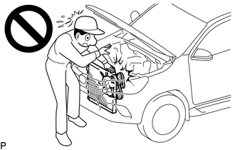
To prevent injury due to contact with an operating fan and generator V-belt or cooling fan, keep your hands and clothing away from the fan and generator V-belt and cooling fans when working in the engine compartment with the engine running.
-
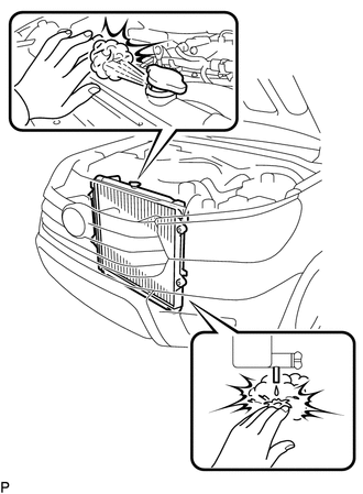
Do not remove the radiator cap sub-assembly, cylinder block drain cock plugs or radiator drain cock plug while the engine and radiator assembly are still hot. Pressurized, hot engine coolant and steam may be released and cause serious burns.
-
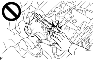
To prevent burns, do not touch the engine, exhaust manifold or other high temperature components while the engine is hot.
-
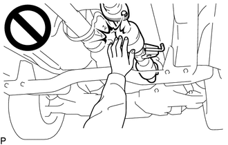
To prevent burns, do not touch the engine, exhaust pipe or other high temperature components while the engine is hot.
PROCEDURE
-
PLACE FRONT WHEELS FACING STRAIGHT AHEAD (for 4WD)
-
DISCHARGE FUEL SYSTEM PRESSURE
-
PRECAUTION
Note
After turning the ignition switch off, waiting time may be required before disconnecting the cable from the battery terminal. Therefore, make sure to read the disconnecting the cable from the battery terminal notice before proceeding with work.
-
DISCONNECT CABLE FROM NEGATIVE BATTERY TERMINAL
Note
When disconnecting the cable, some systems need to be initialized after the cable is reconnected.
-
DRAIN ENGINE COOLANT
-
DRAIN ENGINE OIL
-
DRAIN MANUAL TRANSMISSION OIL (for Manual Transmission)
-
for R151:
-
for R151F:
-
-
DRAIN AUTOMATIC TRANSMISSION FLUID (for Automatic Transmission)
-
for AC60E:
-
for AC60F:
-
-
DRAIN DIFFERENTIAL OIL (for 4WD)
-
REMOVE HOOD SUB-ASSEMBLY
-
Disconnect the washer nozzle hose from the hood sub-assembly.
-
Remove the 4 bolts and hood sub-assembly from the 2 hood hinge assemblies.
-
-
REMOVE AIR CLEANER CAP SUB-ASSEMBLY WITH NO. 1 AIR CLEANER HOSE
-
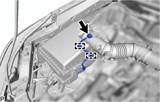
Disconnect the intake mass air flow meter connector and detach the 2 wire harness clamps.
-
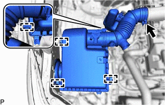
Detach the 4 clamps.
-
Loosen the hose clamp and remove the air cleaner cap sub-assembly with No. 1 air cleaner hose.
-
-
REMOVE AIR CLEANER FILTER ELEMENT SUB-ASSEMBLY
-
Remove the air cleaner filter element sub-assembly from the air cleaner case sub-assembly.
-
-
REMOVE AIR CLEANER CASE SUB-ASSEMBLY
-
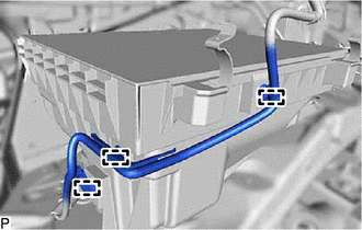
Detach the 3 wire harness clamps.
-
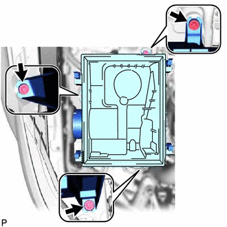
Remove the 3 bolts and air cleaner case sub-assembly.
-
-
REMOVE INTAKE AIR CONNECTOR
-
REMOVE NO. 1 ENGINE UNDER COVER ASSEMBLY
-
REMOVE NO. 2 ENGINE UNDER COVER
-
REMOVE NO. 3 ENGINE UNDER COVER SUB-ASSEMBLY (w/ Cover)
-
REMOVE FRONT UPPER FENDER APRON SEAL LH
-
Remove the 6 clips and front upper fender apron seal LH.
-
-
REMOVE FRONT UPPER FENDER APRON SEAL RH
-
w/ Secondary Air Injection System:
-
Remove the 5 clips and front upper fender apron seal RH.
-
-
w/o Secondary Air Injection System:
-
Remove the 6 clips and front upper fender apron seal RH.
-
-
-
REMOVE FRONT FENDER SEAL LH
-
Remove the 6 clips and front fender seal LH.
-
-
REMOVE FRONT FENDER SEAL RH
-
Remove the 6 clips and front fender seal RH.
-
-
REMOVE RADIATOR SIDE DEFLECTOR LH
-
REMOVE RADIATOR SIDE DEFLECTOR RH
Tech Tips
Use the same procedure described for the LH side.
-
REMOVE NO. 1 RADIATOR AIR GUIDE
-
REMOVE RADIATOR HOSE INLET
-
REMOVE RADIATOR HOSE OUTLET
-
DISCONNECT AIR PUMP INLET (w/ Secondary Air Injection System)
-
REMOVE RADIATOR RESERVOIR
-
REMOVE FAN SHROUD
-
DISCONNECT NO. 1 OIL COOLER INLET HOSE (for Automatic Transmission)
-
DISCONNECT NO. 1 OIL COOLER OUTLET HOSE (for Automatic Transmission)
-
REMOVE RADIATOR ASSEMBLY
-
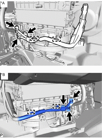
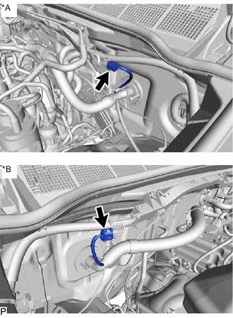
DISCONNECT HEATER HOSE (w/ Heater)
-
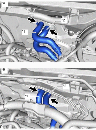
*A for LHD *B for RHD *1 Heater Water Outlet Hose *2 Heater Water Inlet Hose Slide the clamp and disconnect the heater water outlet hose from the heater radiator unit sub-assembly.
-
Slide the clamp and disconnect the heater water inlet hose from the heater radiator unit sub-assembly.
-
-
DISCONNECT VANE PUMP ASSEMBLY
-
Disconnect the power steering oil pressure switch connector.
-
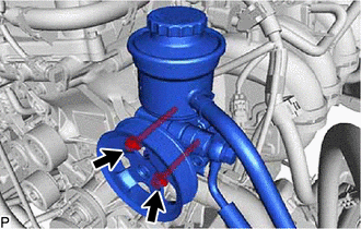
Remove the 2 bolts and disconnect the vane pump assembly.
Note
Do not hit other parts with the pulley when disconnecting the vane pump assembly.
Tech Tips
Be sure to suspend the vane pump assembly securely.
-
-
REMOVE ENGINE OIL LEVEL DIPSTICK
-
REMOVE ENGINE OIL LEVEL DIPSTICK GUIDE
-
Remove the bolt, engine oil level dipstick guide and O-ring.
Note
Cover the engine oil level dipstick guide hole to prevent foreign matter from entering it.
-
-
DISCONNECT COOLER COMPRESSOR ASSEMBLY
-
REMOVE STARTER ASSEMBLY
-
for 2.0 kW Type:
-
except 2.0 kW Type:
-
for BOSCH Made:
-
-
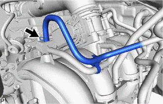
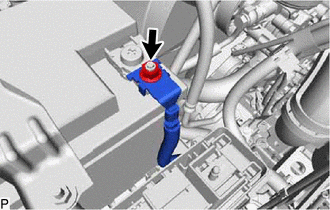
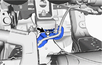
DISCONNECT PURGE LINE HOSE
-
Slide the clamp and disconnect the purge line hose from the purge VSV.
-
-
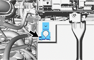
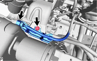
DISCONNECT UNION TO CONNECTOR TUBE HOSE
-
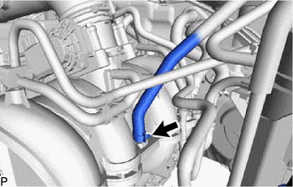
Slide the clamp and disconnect the union to connector tube hose from the intake manifold.
-
-
DISCONNECT NO. 4 AIR INJECTION SYSTEM HOSE (w/ Secondary Air Injection System)
-
DISCONNECT NO. 2 FUEL HOSE
-
DISCONNECT NO. 1 FUEL HOSE
-
REMOVE GLOVE COMPARTMENT DOOR ASSEMBLY
-
REMOVE ECM
-
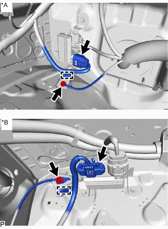
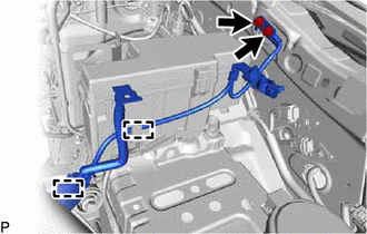
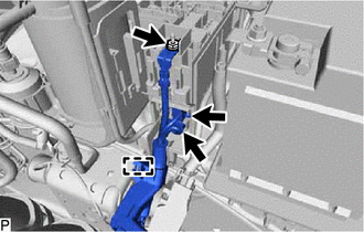
DISCONNECT ENGINE WIRE
-
*A for LHD *B for RHD Detach the 2 clamps and disconnect the 3 connectors from the instrument panel wire.
-
*A for LHD *B for RHD w/ Secondary Air Injection System:
-
Disconnect the air injection control driver connector.
-
Detach the clamp.
-
Remove the bolt and disconnect the engine wire from the air injection control bracket.
-
-
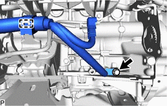
*A for LHD *B for RHD w/o Secondary Air Injection System:
-
Remove the bolt and disconnect the engine wire from the air injection control bracket.
-
-
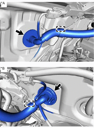
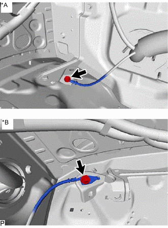
*A for LHD *B for RHD Detach the grommet and pull out the engine wire from the cabin.
-
*A for LHD *B for RHD Disconnect the connector from the engine room main wire.
-
Remove the nut and disconnect the engine room main wire from the positive (+) battery terminal.
-
Loosen the nut and remove the positive (+) battery terminal.
-
Loosen the 2 nuts and remove the battery hold down clamp.
-
Remove the battery.
-
Remove the battery tray.
-
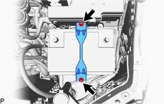
Detach the 2 clamps and remove the 2 bolts and disconnect the No. 2 engine wire.
-
Detach the clamp and remove the bolt and No. 2 engine wire.
-
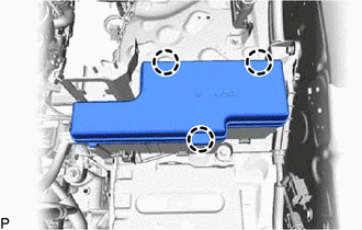
Detach the 3 claws and remove the No. 1 relay block cover upper from the engine room relay block.
-
Detach the 2 claws and remove the No. 1 relay block cover side from the engine room relay block.
-
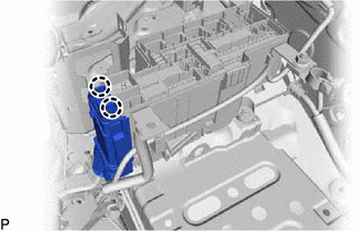
Remove the nut and disconnect the engine wire from the engine room relay block.
-
Disconnect the 2 connectors from the engine room relay block.
-
Detach the clamp.
-
Remove the bolt and disconnect the wire clamp from the front engine mounting bracket LH.
-
Disconnect the air fuel ratio sensor connector.
-
Remove the bolt and disconnect the sensor bracket from the right side of the frame.
-
-
REMOVE FRONT EXHAUST PIPE ASSEMBLY
-
REMOVE PROPELLER SHAFT GUARD (for 4WD)
-
for TSAM Made:
-
except TSAM Made:
-
-
REMOVE FRONT PROPELLER SHAFT ASSEMBLY (for 4WD)
-
for TSAM Made:
-
except TSAM Made:
-
-
REMOVE PROPELLER SHAFT GUARD
-
for TSAM Made:
-
for TMT Made:
-
for TMMIN Made:
-
-
REMOVE PROPELLER SHAFT WITH CENTER BEARING ASSEMBLY (for Pre-Runner)
-
for TSAM Made:
-
for TMT Made:
-
for TMMIN Made:
-
-
REMOVE PROPELLER SHAFT WITH CENTER BEARING ASSEMBLY (for 4WD)
-
for TSAM Made:
-
for TMT Made:
-
for TMMIN Made:
-
-
REMOVE FRONT AXLE HUB GREASE CAP LH (for 4WD)
-
REMOVE FRONT AXLE SHAFT NUT LH (for 4WD)
-
DISCONNECT FRONT SPEED SENSOR LH (for 4WD)
-
DISCONNECT TIE ROD END SUB-ASSEMBLY LH (for 4WD)
-
DISCONNECT FRONT LOWER NO. 1 SUSPENSION ARM ASSEMBLY LH (for 4WD)
-
REMOVE FRONT DRIVE SHAFT ASSEMBLY LH (for 4WD)
-
REMOVE FRONT DRIVE SHAFT ASSEMBLY RH (for 4WD)
Tech Tips
Use the same procedure described for the LH side.
-
REMOVE FRONT DRIVE SHAFT HOLE SNAP RING (for 4WD)
-
SECURE STEERING WHEEL ASSEMBLY (for 4WD)
-
DISCONNECT STEERING SLIDING YOKE (for 4WD)
-
REMOVE POWER STEERING LINK ASSEMBLY (for 4WD)
-
REMOVE FRONT DIFFERENTIAL CARRIER ASSEMBLY (for 4WD)
-
REMOVE MANUAL TRANSMISSION UNIT ASSEMBLY (for Manual Transmission)
-
for R151:
-
for R151F:
-
-
REMOVE AUTOMATIC TRANSMISSION ASSEMBLY (for Automatic Transmission)
-
for AC60E:
-
for AC60F:
-
-
REMOVE CLUTCH COVER ASSEMBLY (for Manual Transmission)
-
REMOVE CLUTCH DISC ASSEMBLY (for Manual Transmission)
-
REMOVE FLYWHEEL SUB-ASSEMBLY (for Manual Transmission)
-
REMOVE DRIVE PLATE AND RING GEAR SUB-ASSEMBLY (for Automatic Transmission)
-
REMOVE REAR END PLATE
-
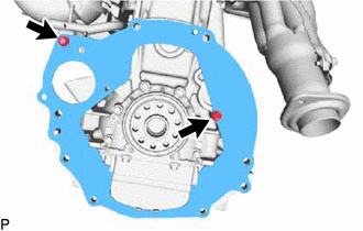
Remove the bolt and disconnect the No. 1 water by-pass pipe from the rear end plate.
-
Remove the bolt and rear end plate from the cylinder block sub-assembly.
-
-
INSTALL ENGINE HANGER
-
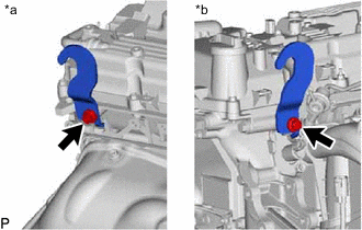
*a Rear Side *b Front Side Install the 2 engine hangers with the 2 bolts as shown in the illustration.
- Torque:
- 42 N*m { 428 kgf*cm, 31 ft.*lbf }
Tech Tips
No. 1 Engine Hanger 12281-0C010
12281-0C030
Bolt 90119-T0388
91672-81025
-
-
REMOVE ENGINE ASSEMBLY
-
Attach an engine sling device and hang the engine assembly with a chain block.
-
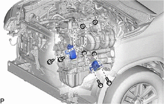
Remove the 4 bolts and 4 nuts from the body.
-
Remove the engine assembly by operating the engine sling device and chain block.
Note
-
Make sure that the engine is clear of all wiring and hoses.
-
While lowering the engine from the vehicle, do not allow it to contact the vehicle.
-
-
-
INSTALL ENGINE ASSEMBLY TO ENGINE STAND
-
Install the engine to an engine stand with bolts.
Note
-
Pay attention to the angle of the sling device as the engine assembly or engine hangers may be damaged or deformed if the angle is incorrect.
-
With the exception of installing the engine assembly to an engine stand or removing the engine assembly from an engine stand, do not perform any work on the engine while it is suspended, as doing so is dangerous.
-
-
Remove the 2 bolts and 2 engine hangers.
-
-
REMOVE ENGINE WIRE
-
Remove the engine wire from the engine assembly.
-
-
REMOVE FRONT ENGINE MOUNTING HEAT INSULATOR RH
-
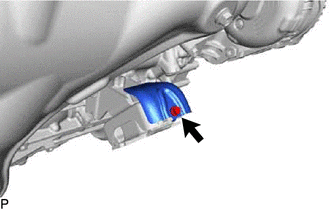
Remove the bolt and front engine mounting heat insulator RH from the front engine mounting insulator.
-
-
REMOVE FRONT ENGINE MOUNTING INSULATOR
Tech Tips
Perform this procedure only when replacement of the front engine mounting insulator is necessary.
-
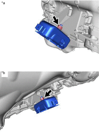
*a LH Side *b RH Side Remove the 2 nuts and 2 front engine mounting insulators from the 2 front engine mounting brackets.
-