ENGINE UNIT REMOVAL

PROCEDURE
-
REMOVE ENGINE WIRE (for LHD)
-
Disconnect the connectors and wire harness from the engine.
-
Remove the 2 bolts and wire harness from the engine.
-
-
REMOVE ENGINE WIRE (for RHD)
-
Disconnect the connectors and wire harness from the engine.
-
Remove the 2 bolts and wire harness from the engine.
-
-
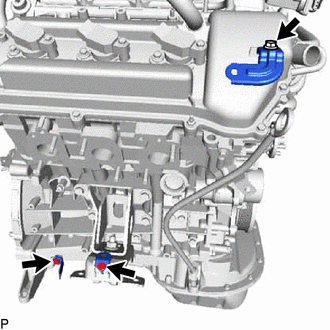
REMOVE V-BANK COVER BRACKET SUB-ASSEMBLY
-
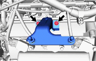
Remove the 2 bolts and V-bank cover bracket sub-assembly.
-
-
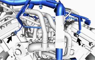
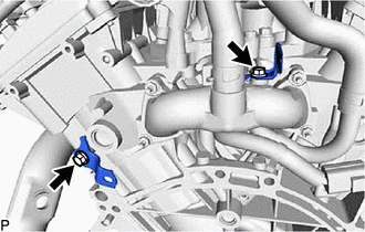
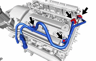
REMOVE WIRE HARNESS CLAMP BRACKET
-
for Rear Side:
-
Remove the 2 bolts and 2 wire harness clamp brackets.
-
-
for RH Side:
-
Remove the 3 bolts and 3 wire harness clamp brackets.
-
-
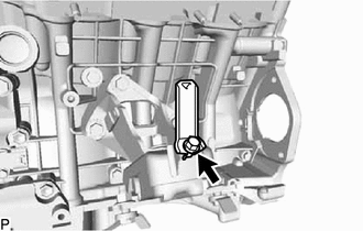
for LH Side:
-
Remove the bolt and wire harness clamp bracket.
-
-
-
REMOVE WATER HOSE SUB-ASSEMBLY
-
Slide the 2 clamps and remove the water hose sub-assembly.
-
-
REMOVE PCV HOSE
-
REMOVE NO. 2 PCV HOSE
-
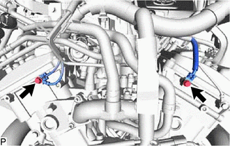
REMOVE NO. 1 FUEL PIPE SUB-ASSEMBLY AND NO. 2 FUEL PIPE SUB-ASSEMBLY
-
Remove the No. 2 fuel pipe clamp and disconnect the No. 1 fuel pipe sub-assembly from the fuel delivery pipe sub-assembly.
-
Remove the No. 2 fuel pipe clamp and disconnect the No. 2 fuel pipe sub-assembly from the fuel pressure regulator assembly.
-
Remove the 2 bolts, No. 1 fuel pipe sub-assembly and No. 2 fuel pipe sub-assembly.
-
-
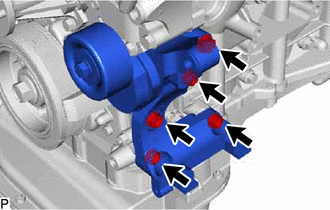
REMOVE FRONT NO. 1 ENGINE MOUNTING BRACKET RH
-
Remove the 4 bolts and front No. 1 engine mounting bracket RH.
-
-
REMOVE FRONT NO. 1 ENGINE MOUNTING BRACKET LH
-
Remove the 3 bolts and front No. 1 engine mounting bracket LH.
-
-
REMOVE V-RIBBED BELT TENSIONER ASSEMBLY
-
Remove the 5 bolts and V-ribbed belt tensioner assembly.
-
-
REMOVE FUEL DELIVERY PIPE SUB-ASSEMBLY
-
REMOVE FUEL INJECTOR ASSEMBLY
-
REMOVE INTAKE MANIFOLD
-
REMOVE IGNITION COIL ASSEMBLY
-
REMOVE ENGINE OIL LEVEL DIPSTICK GUIDE
-
Remove the engine oil level dipstick.
-
Remove the bolt and pull out the engine oil level dipstick guide.
-
Remove the O-ring from the engine oil level dipstick guide.
-
-
REMOVE NO. 2 IDLER PULLEY SUB-ASSEMBLY
-
REMOVE NO. 1 IDLER PULLEY SUB-ASSEMBLY
-
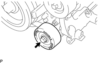
Remove the bolt and No. 1 idler pulley sub-assembly.
-