МЕХАНИЧЕСКАЯ ТРАНСМИССИЯ В СБОРЕ УСТАНОВКА
CAUTION / NOTICE / HINT
CAUTION:
The manual transmission assembly is very heavy. Be sure to follow the procedure described in the repair manual, or the transmission jack may suddenly drop or a part may fall.
PROCEDURE
-
INSTALL TRANSFER ASSEMBLY
-
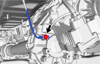
INSTALL WIRE HARNESS CLAMP BRACKET
-
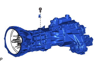
Install the wire harness clamp bracket to the manual transmission unit assembly with the bolt.
- Torque:
- 64 N*m { 653 kgf*cm, 47 ft.*lbf }
-
-
INSTALL TRANSMISSION BREATHER SUB-ASSEMBLY
-
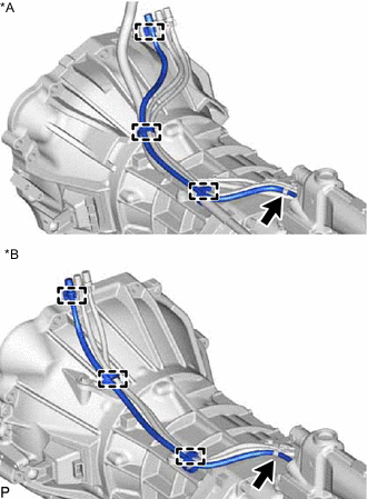
*A for 2TR-FE *B for 5L-E Connect the 3 clamps and install the transmission breather sub-assembly.
-
-
INSTALL MANUAL TRANSMISSION UNIT ASSEMBLY
CAUTION:
The manual transmission unit assembly is very heavy. Be sure to follow the procedure described in the repair manual, or the transmission jack may suddenly drop or a part may fall.
-
Make sure that the knock pins are not loose, bent, damaged or scratched.
-
Operate the transmission jack and install the manual transmission unit assembly to the vehicle.
CAUTION:
Do not raise the manual transmission unit assembly more than necessary. If the manual transmission unit assembly is raised excessively, the vehicle may also be lifted up.
Note
Make sure that the manual transmission unit assembly is clear of all wiring and hoses.
-
Align the input shaft with the clutch disc and install the manual transmission unit assembly to the engine.
-
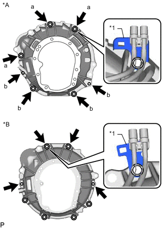
*A for 2TR-FE *B for 5L-E *1 Transmission Breather Bracket for 2TR-FE:
Install the transmission breather bracket and 7 bolts.
- Torque:
- for bolt a
- 71.5 N*m { 729 kgf*cm, 53 ft.*lbf }
- for bolt b
- 37.2 N*m { 379 kgf*cm, 27 ft.*lbf }
-
for 5L-E:
Install the transmission breather bracket and 4 bolts.
- Torque:
- 71.5 N*m { 729 kgf*cm, 53 ft.*lbf }
-
-
CONNECT WIRE HARNESS
-
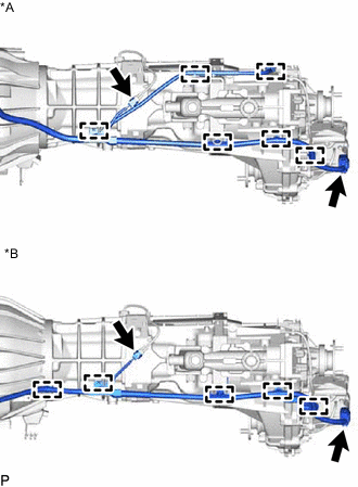
*A for 2TR-FE *B for 5L-E for 2TR-FE:
Connect the 6 clamps and 2 connector.
-
for 5L-E:
Connect the 4 clamps and 2 connectors.
-
-
INSTALL REAR ENGINE MOUNTING INSULATOR
-
Install the rear engine mounting insulator with the 4 bolts.
- Torque:
- 47 N*m { 479 kgf*cm, 35 ft.*lbf }
-
-
INSTALL NO. 3 FRAME CROSSMEMBER SUB-ASSEMBLY
-
Install the No. 3 frame crossmember sub-assembly with the 4 bolts and 4 nuts.
- Torque:
- 57 N*m { 581 kgf*cm, 42 ft.*lbf }
-
Connect the No. 3 frame crossmember sub-assembly to the rear engine mounting insulator.
- Torque:
- 18.5 N*m { 189 kgf*cm, 14 ft.*lbf }
-
-
INSTALL STARTER ASSEMBLY (for 5L-E)
-
INSTALL STARTER ASSEMBLY (for 2TR-FE)
-
for 2.0 kW Type:
-
except 2.0 kW Type:
-
-
CONNECT CLUTCH RELEASE CYLINDER ASSEMBLY
-
CONNECT GROUND CABLE
-
Connect the ground cable with the bolt.
- Torque:
- 19.5 N*m { 199 kgf*cm, 14 ft.*lbf }
-
-
INSTALL STIFFENER PLATE (for 5L-E)
-
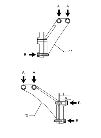
*1 Stiffener Plate RH *2 Stiffener Plate LH Install the stiffener plate RH with the 3 bolts.
- Torque:
- for bolt A
- 37.3 N*m { 380 kgf*cm, 28 ft.*lbf }
- for bolt B
- 68.7 N*m { 701 kgf*cm, 51 ft.*lbf }
-
Install the stiffener plate LH with the 4 bolts.
- Torque:
- for bolt A
- 37.3 N*m { 380 kgf*cm, 28 ft.*lbf }
- for bolt B
- 68.7 N*m { 701 kgf*cm, 51 ft.*lbf }
-
-
INSTALL MANIFOLD STAY (for 2TR-FE)
-
INSTALL FRONT EXHAUST PIPE ASSEMBLY
-
for 2TR-FE:
-
for 5L-E:
-
-
INSTALL PROPELLER SHAFT WITH CENTER BEARING ASSEMBLY
-
for TMT Made:
-
for TSAM Made:
-
-
INSTALL FRONT PROPELLER SHAFT ASSEMBLY
-
for TMT Made:
-
for TSAM Made:
-
-
INSTALL NO. 3 ENGINE UNDER COVER SUB-ASSEMBLY
-
INSTALL NO. 2 ENGINE UNDER COVER
-
INSTALL NO. 1 ENGINE UNDER COVER ASSEMBLY
-
ADD MANUAL TRANSMISSION OIL
-
INSTALL FLOOR SHIFT SHIFT LEVER ASSEMBLY
-
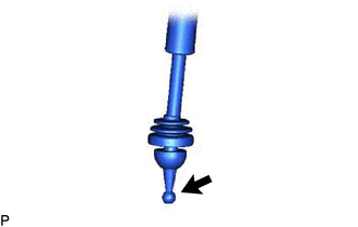

MP grease Apply MP grease to the tip of the shift lever.
-
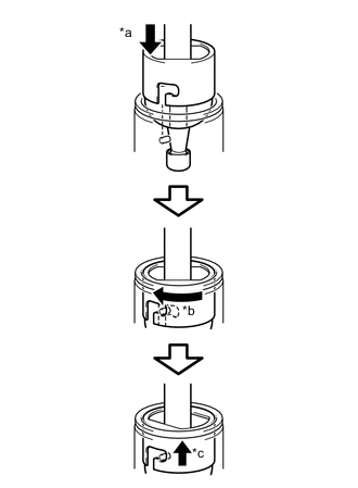
*a Press down *b Clockwise *c Lock Cover the shift lever cap with a cloth.
-
While pressing down on the shift lever cap, turn it clockwise to install the shift lever.
-
Attach the shift lever cap boot.
-
-
INSTALL SHIFT LEVER BOOT ASSEMBLY
-
Install the shift lever boot assembly with the 6 screws and 4 clips.
-
-
INSTALL CONSOLE BOX ASSEMBLY (w/ Console Box Lid)
-
INSTALL FRONT CONSOLE BOX (w/o Console Box Lid)
-
CONNECT CABLE TO NEGATIVE BATTERY TERMINAL
Note
When disconnecting the cable, some systems need to be initialized after the cable is reconnected.