СИСТЕМА ECD, Diagnostic DTC:P0046
| DTC Code | DTC Name |
|---|---|
| P0046 | Turbocharger / Supercharger Boost Control "A" Circuit Range / Performance |
DESCRIPTION
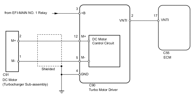
Variable nozzle vane type turbocharger consists primarily of a compressor wheel, turbine wheel, nozzle vane, unison ring, DC motor and nozzle vane position sensor.
The ECM outputs a signal to the turbo motor driver, which actuates the DC motor, to control the nozzle vane position.
| DTC No. | Detection Item | DTC Detection Condition | Trouble Area | MIL | Memory |
|---|---|---|---|---|---|
| P0046 | Turbocharger / Supercharger Boost Control Solenoid Circuit Range / Performance | Either of following conditions met:
|
|
Comes on | DTC stored |
CONFIRMATION DRIVING PATTERN
| DTC Detection Drive Pattern | Drive the vehicle with a city driving pattern at least 10 minutes. |
WIRING DIAGRAM
CAUTION / NOTICE / HINT
Tech Tips
Read freeze frame data using the GTS. Freeze frame data records the engine condition when malfunctions are detected. When troubleshooting, freeze frame data can help determine if the vehicle was moving or stationary, if the engine was warmed up or not, and other data from the time the malfunction occurred.
PROCEDURE
-
CHECK FOR ANY OTHER DTCS OUTPUT (IN ADDITION TO P0046)
-
Connect the GTS to the DLC3.
-
Turn the ignition switch to ON and turn the GTS on.
-
Enter the following menus: Powertrain / Engine / Troble codes.
Powertrain > Engine > Trouble Codes -
Read the DTCs.
Result Result Proceed to P0046 is output A P0046 and other DTCs are output B Tech Tips
If any DTCs other than P0046 are output, troubleshoot those DTCs first.
B 
GO TO DTC CHART Click here
A 
-
-
CHECK TURBOCHARGER SUB-ASSEMBLY (DC MOTOR OPERATION)
-
Turn the ignition switch to ON.
-
Turn the ignition switch off and check the DC motor operation (check the operation link movement).
Tech Tips
When it is necessary to repeat this inspection, wait 30 seconds or more with the ignition switch off before performing the inspection.
OK When ignition switch is turned off, operation link moves as shown in A through D in illustration below. Operation link and motor rod move smoothly when moving from position shown in A to that shown in B, and from position shown in B to that shown in C. 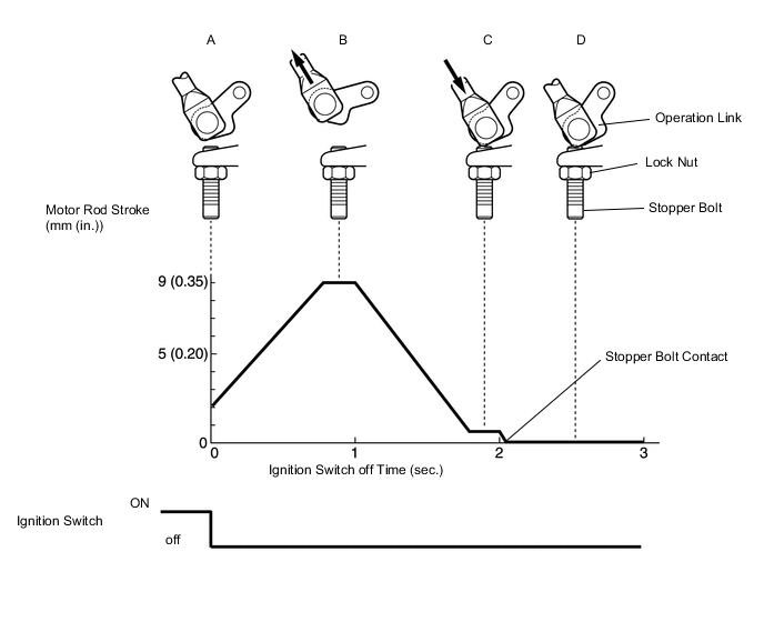
Result Proceed to OK NG
OK
CHECK FOR INTERMITTENT PROBLEMS Click here
NG
-
-
CHECK TURBO MOTOR DRIVER
-
Voltage Inspection
-
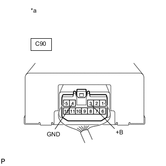
*a Component with harness connected
(Turbo Motor Driver)
Turn the ignition switch to ON.
-
Measure the voltage according to the value(s) in the table below.
Standard Voltage Tester Connection Condition Specified Condition C90-3 (+B) - C90-4 (GND) Always 11 to 14 V
-
-
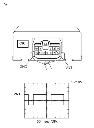
*a Component with harness connected
(Turbo Motor Driver)
Output Waveform Inspection
-
Turn the ignition switch to ON.
-
Check the waveform of the ECM connectors using an oscilloscope.
OK Tester Connection Switch Condition Specified Condition C90-2 (VNTI) - C90-4 (GND) Ignition switch ON Correct waveform is as shown
Result Proceed to OK NG -
NG 
REPLACE TURBO MOTOR DRIVER Click here
OK
-
-
INSPECT TURBOCHARGER SUB-ASSEMBLY (DC MOTOR RESISTANCE)
-
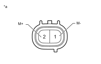
*a Component without harness connected
(DC Motor)
Disconnect the DC motor connector.
-
Measure the DC motor resistance.
Standard resistance 1 to 100 Ω Result Proceed to OK NG
NG
REPLACE TURBOCHARGER SUB-ASSEMBLY Click here
OK
-
-
CHECK HARNESS AND CONNECTOR (DC MOTOR - TURBO MOTOR DRIVER)
-
Disconnect the DC motor connector.
-
Disconnect the turbo motor driver connector.
-
Measure the resistance according to the value(s) in the table below.
Standard Resistance Tester Connection Condition Specified Condition C90-12 (M+) - C91-2 (M+) Always Below 1 Ω C90-5 (M-) - C91-1 (M-) Always Below 1 Ω C90-12 (M+) or C91-2 (M+) - Body ground Always 10 kΩ or higher C90-5 (M-) or C91-1 (M-) - Body ground Always 10 kΩ or higher -
Reconnect the turbo motor driver connector.
-
Reconnect the DC motor connector.
Result Proceed to OK NG
NG
REPAIR OR REPLACE HARNESS OR CONNECTOR Click here
OK
-
-
CHECK WHETHER DTC OUTPUT RECURS (DTC P0046)
-
Connect the GTS to the DLC3.
-
Turn the ignition switch to ON and turn the GTS on.
-
Clear the DTCs.
Powertrain > Engine > Clear DTCs -
Start the engine.
-
Drive the vehicle with a city driving pattern at least 10 minutes.
-
Enter the following menus: Powertrain / Engine / Trouble Codes.
Powertrain > Engine > Trouble Codes -
Read the DTCs.
Result Result Proceed to P0046 is output A No DTC is output B
A
CHECK FOR INTERMITTENT PROBLEMS Click here
B
END
-
-
REPLACE TURBO MOTOR DRIVER
-
Replace turbo motor driver.
Result Proceed to NEXT
NEXT
GO TO STEP 10 Click here
-
-
REPLACE TURBOCHARGER SUB-ASSEMBLY
-
Replace turbocharger sub-assembly.
Result Proceed to NEXT
NEXT
GO TO STEP 10 Click here
-
-
REPAIR OR REPLACE HARNESS OR CONNECTOR
-
Repair or replace the harness or connector.
Result Proceed to NEXT
NEXT
-
-
CONFIRM WHETHER MALFUNCTION HAS BEEN SUCCESSFULLY REPAIRED
-
Connect the GTS to the DLC3.
-
Turn the ignition switch to ON and turn the GTS on.
-
Clear the DTCs.
Powertrain > Engine > Clear DTCs -
Start the engine.
-
Drive the vehicle with a city driving pattern at least 10 minutes.
-
Enter the following menus: Powertrain / Engine / Trouble Codes.
Powertrain > Engine > Trouble Codes -
Confirm that the DTC is not output again.
Result Proceed to NEXT
NEXT
END
-