LIGHTING SYSTEM Front Fog Light Circuit
DESCRIPTION
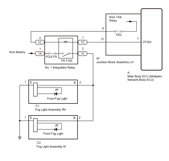
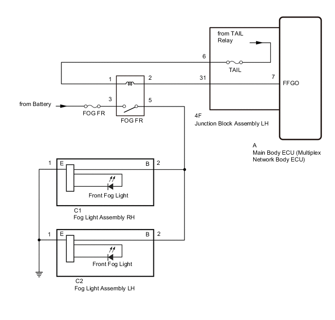
Illumination of the front fog lights is controlled by the main body ECU (multiplex network body ECU).
WIRING DIAGRAM
-
for 2AR-FE:
-
for 2GR-FKS:
CAUTION / NOTICE / HINT
Note
-
Inspect the fuses for circuits related to this system before performing the following procedure.
-
Before performing troubleshooting, check that the taillight circuit operates properly.
-
If the main body ECU (multiplex network body ECU) is replaced, refer to the Service Bulletin.
PROCEDURE
-
PERFORM ACTIVE TEST USING GTS
-
Using the GTS, perform the Active Test.
Body Electrical > Main Body > Active TestTester Display Measurement Item Control Range Diagnostic Note Front Fog Light Relay Front fog light relay ON or OFF The headlight dimmer switch (light control switch) is in the tail position.
Body Electrical > Main Body > Active TestTester Display Front Fog Light Relay Tech Tips
Check the operation with the taillights illuminated.
Result Result Proceed to The Active Test is performed normally A The Active Test is not performed normally for both fog lights (for 2AR-FE) B The Active Test is not performed normally for both fog lights (for 2GR-FKS) C
A 
PROCEED TO NEXT SUSPECTED AREA SHOWN IN PROBLEM SYMPTOMS TABLE Click here
C 
INSPECT FOG LIGHT RELAY (FOG FR) Click here
B 
-
-
INSPECT NO. 1 INTEGRATION RELAY (FR FOG RELAY)
-
Remove the No. 1 integration relay.
-
Inspect the fog light relay.
Result Proceed to OK NG
NG
REPLACE NO. 1 INTEGRATION RELAY Click here
OK
-
-
CHECK HARNESS AND CONNECTOR (NO. 1 INTEGRATION RELAY - BATTERY)
-
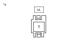
*a Front view of wire harness connector
(to No. 1 Integration Relay)
Disconnect the No. 1 integration relay connector.
-
Measure the voltage according to the value(s) in the table below.
Standard Voltage Tester Connection Condition Specified Condition 1A-1 - Body ground Always 11 to 14 V Result Proceed to OK NG
NG
REPAIR OR REPLACE HARNESS OR CONNECTOR
OK
-
-
CHECK HARNESS AND CONNECTOR (TAILLIGHT RELAY [TAIL RELAY] - NO. 1 INTEGRATION RELAY)
-
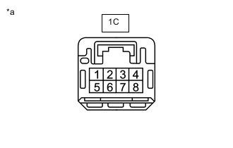
*a Front view of wire harness connector
(to No. 1 Integration Relay)
Disconnect the No. 1 integration relay connector.
-
Measure the voltage according to the value(s) in the table below.
Standard Voltage Tester Connection Switch Condition Specified Condition 1C-3 - Body ground Headlight dimmer switch (light control switch) off → TAIL or HEAD Below 1 V → 11 to 14 V Result Proceed to OK NG
NG
CHECK HARNESS AND CONNECTOR (NO. 1 INTEGRATION RELAY - JUNCTION BLOCK ASSEMBLY LH) Click here
OK
-
-
CHECK HARNESS AND CONNECTOR (NO. 1 INTEGRATION RELAY - FOG LIGHT ASSEMBLY RH)
-
Disconnect the 1C No. 1 integration relay connector.
-
Disconnect the C1 fog light assembly RH connector.
-
Disconnect the C2 fog light assembly LH connector.
-
Measure the resistance according to the value(s) in the table below.
Standard Resistance Tester Connection Condition Specified Condition 1C-2 - C1-2 (B) Always Below 1 Ω 1C-2 or C1-2 (B) - Body ground Always 10 kΩ or higher Result Proceed to OK NG
NG
REPAIR OR REPLACE HARNESS OR CONNECTOR
OK
-
-
CHECK HARNESS AND CONNECTOR (NO. 1 INTEGRATION RELAY - MAIN BODY ECU [MULTIPLEX NETWORK BODY ECU])
-
Disconnect the 1C No. 1 integration relay connector.
-
Remove the main body ECU (multiplex network body ECU) from the junction block assembly LH.
-
Connect the 4F junction block assembly LH connector.
-
Measure the resistance according to the value(s) in the table below.
Standard Resistance Tester Connection Condition Specified Condition 1C-1 - A-7 (FFGO) Always Below 1 Ω 1C-1 or A-7 (FFGO) - Body ground Always 10 kΩ or higher Result Proceed to OK NG
OK
REPLACE MAIN BODY ECU (MULTIPLEX NETWORK BODY ECU) Click here
NG
-
-
CHECK HARNESS AND CONNECTOR (NO. 1 INTEGRATION RELAY - JUNCTION BLOCK ASSEMBLY LH)
-
Disconnect the 1C No. 1 integration relay connector.
-
Disconnect the 4F junction block assembly LH connector.
-
Measure the resistance according to the value(s) in the table below.
Standard Resistance Tester Connection Condition Specified Condition 1C-1 - 4F-31 Always Below 1 Ω 1C-1 or 4F-31 - Body ground Always 10 kΩ or higher Result Proceed to OK NG
OK
REPLACE JUNCTION BLOCK ASSEMBLY LH Click here
NG
REPAIR OR REPLACE HARNESS OR CONNECTOR
-
-
CHECK HARNESS AND CONNECTOR (NO. 1 INTEGRATION RELAY - JUNCTION BLOCK ASSEMBLY LH)
-
Disconnect the 1C No. 1 integration relay connector.
-
Disconnect the 4F junction block assembly LH connector.
-
Measure the resistance according to the value(s) in the table below.
Standard Resistance Tester Connection Condition Specified Condition 1C-3 - 4F-6 Always Below 1 Ω 1C-3 or 4F-6 - Body ground Always 10 kΩ or higher Result Proceed to OK NG
OK
REPLACE JUNCTION BLOCK ASSEMBLY LH Click here
NG
REPAIR OR REPLACE HARNESS OR CONNECTOR
-
-
INSPECT FOG LIGHT RELAY (FOG FR)
-
Remove the fog light relay (FOG FR) from the No. 2 engine room relay block.
-
Inspect the fog light relay (FOG FR).
Result Proceed to OK NG
NG
REPLACE FOG LIGHT RELAY (FOG FR)
OK
-
-
CHECK HARNESS AND CONNECTOR (FOG LIGHT RELAY [FOG FR] - BATTERY)
-
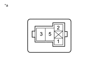
*a Front view of wire harness connector
(to Fog Light Relay [FOG FR])
Remove the fog light relay (FOG FR) from the No. 2 engine room relay block.
-
Measure the voltage according to the value(s) in the table below.
Standard Voltage Tester Connection Condition Specified Condition Fog light relay (FOG FR) terminal 3 - Body ground Always 11 to 14 V Result Proceed to OK NG
NG
REPAIR OR REPLACE HARNESS OR CONNECTOR
OK
-
-
CHECK HARNESS AND CONNECTOR (TAILLIGHT RELAY [TAIL RELAY] - FOG LIGHT RELAY [FOG FR])
-
*a Front view of wire harness connector
(to Fog Light Relay [FOG FR])
Remove the fog light relay (FOG FR) from the No. 2 engine room relay block.
-
Measure the voltage according to the value(s) in the table below.
Standard Voltage Tester Connection Switch Condition Specified Condition Fog light relay (FOG FR) terminal 1 - Body ground Headlight dimmer switch (light control switch) off → TAIL or HEAD Below 1 V → 11 to 14 V Result Proceed to OK NG
NG
CHECK HARNESS AND CONNECTOR (FOG LIGHT RELAY [FOG FR] - JUNCTION BLOCK ASSEMBLY LH) Click here
OK
-
-
CHECK HARNESS AND CONNECTOR (FOG LIGHT RELAY [FOG FR] - FOG LIGHT ASSEMBLY RH)
-
Remove the fog light relay (FOG FR) from the No. 2 engine room relay block.
-
Disconnect the C1 fog light assembly RH connector.
-
Measure the resistance according to the value(s) in the table below.
Standard Resistance Tester Connection Condition Specified Condition Fog light relay (FOG FR) terminal 5 - C1-2 (B) Always Below 1 Ω Fog light relay (FOG FR) terminal 5 or C1-2 (B) - Body ground Always 10 kΩ or higher Result Proceed to OK NG
NG
REPAIR OR REPLACE HARNESS OR CONNECTOR
OK
-
-
CHECK HARNESS AND CONNECTOR (FOG LIGHT RELAY [FOG FR] - MAIN BODY ECU [MULTIPLEX NETWORK BODY ECU])
-
Remove the fog light relay (FOG FR) from the No. 2 engine room relay block.
-
Remove the main body ECU (multiplex network body ECU) from the junction block assembly LH.
-
Connect the 4F junction block assembly LH connector.
-
Measure the resistance according to the value(s) in the table below.
Standard Resistance Tester Connection Condition Specified Condition Fog light relay (FOG FR) terminal 2 - A-7 (FFGO) Always Below 1 Ω Fog light relay (FOG FR) terminal 2 or A-7 (FFGO) - Body ground Always 10 kΩ or higher Result Proceed to OK NG
OK
REPLACE MAIN BODY ECU (MULTIPLEX NETWORK BODY ECU) Click here
NG
-
-
CHECK HARNESS AND CONNECTOR (FOG LIGHT RELAY [FOG FR] - JUNCTION BLOCK ASSEMBLY LH)
-
Remove the fog light relay (FOG FR) from the No. 2 engine room relay block.
-
Disconnect the 4F junction block assembly LH connector.
-
Measure the resistance according to the value(s) in the table below.
Standard Resistance Tester Connection Condition Specified Condition Fog light relay (FOG FR) terminal 2 - 4F-31 Always Below 1 Ω Fog light relay (FOG FR) terminal 2 or 4F-31 - Body ground Always 10 kΩ or higher Result Proceed to OK NG
OK
REPLACE JUNCTION BLOCK ASSEMBLY LH Click here
NG
REPAIR OR REPLACE HARNESS OR CONNECTOR
-
-
CHECK HARNESS AND CONNECTOR (FOG LIGHT RELAY [FOG FR] - JUNCTION BLOCK ASSEMBLY LH)
-
Remove the fog light relay (FOG FR) from the No. 2 engine room relay block.
-
Disconnect the 4F junction block assembly LH connector.
-
Measure the resistance according to the value(s) in the table below.
Standard Resistance Tester Connection Condition Specified Condition Fog light relay (FOG FR) terminal 1 - 4F-6 Always Below 1 Ω Fog light relay (FOG FR) terminal 1 or 4F-6 - Body ground Always 10 kΩ or higher Result Proceed to OK NG
OK
REPLACE JUNCTION BLOCK ASSEMBLY LH Click here
NG
REPAIR OR REPLACE HARNESS OR CONNECTOR
-