BRAKE ACTUATOR INSTALLATION
PROCEDURE
-
INSTALL BRAKE ACTUATOR BOLT CUSHION
-
Install the 3 brake actuator bolt cushions to the brake actuator bracket assembly.
-
Install the 3 brake actuator case collars to the brake actuator bolt cushions.
Note
Make sure the brake actuator case collars are in full contact with the brake actuator bolt cushions.
-
-
INSTALL BRAKE ACTUATOR ASSEMBLY
-
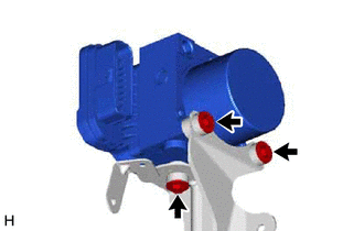
Install the brake actuator assembly to the brake actuator bracket assembly with the 3 bolts.
- Torque:
- 5.4 N*m { 55 kgf*cm, 48 in.*lbf }
Note
-
Do not remove the hole plugs of a new brake actuator assembly before connecting the brake lines because the brake actuator assembly is filled with brake fluid.
-
Do not hold the brake actuator assembly by the connector.
-
-
INSTALL BRAKE ACTUATOR WITH BRACKET
-
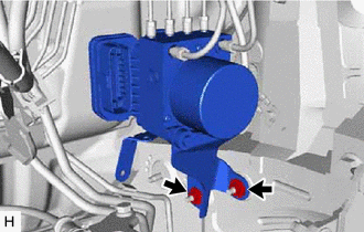
Install the brake actuator with bracket to the vehicle body with the 2 nuts.
- Torque:
- 19 N*m { 194 kgf*cm, 14 ft.*lbf }
Note
-
Do not damage the brake lines.
-
Do not hold the brake actuator with bracket by the connector.
Tech Tips
-
Install the brake actuator with bracket while avoiding the brake lines.
-
for 2AR-FE:
Hold the engine wire to insert the tool from the bottom of the vehicle.
-
for 2AR-FE:
-
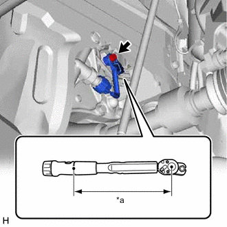
*a Torque Wrench Fulcrum Length Using a union nut wrench, install the engine wire to the engine assembly with transaxle with the bolt.
- Torque:
- Specified tightening torque
- 13 N*m { 133 kgf*cm, 10 ft.*lbf }
Tech Tips
-
Calculate the torque wrench reading when changing the fulcrum length of the torque wrench.
-
When using a union nut wrench (fulcrum length of 22 mm (0.866 in.)) + torque wrench (fulcrum length of 162 mm (6.38 in.)):
11.5 N*m (117 kgf*cm, 8 ft.*lbf)
-
-

Engage the clamp to the brake actuator bracket assembly.
-
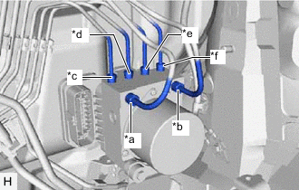
*a for LHD: From 1st Chamber of Brake Master Cylinder Sub-assembly
for RHD: From 2nd Chamber of Brake Master Cylinder Sub-assembly
*b for LHD: From 2nd Chamber of Brake Master Cylinder Sub-assembly
for RHD: From 1st Chamber of Brake Master Cylinder Sub-assembly
*c To Front Wheel Cylinder Assembly LH *d To Rear Wheel Cylinder Assembly RH *e To Rear Wheel Cylinder Assembly LH *f To Front Wheel Cylinder Assembly RH Temporarily tighten each brake line to the correct position on the brake actuator assembly as shown in the illustration.
-
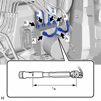
*a Torque Wrench Fulcrum Length Using a union nut wrench, fully tighten each brake line.
- Torque:
- Specified tightening torque (A)
- 19.5 N*m { 199 kgf*cm, 14 ft.*lbf }
- Specified tightening torque (B)
- 15.2 N*m { 155 kgf*cm, 11 ft.*lbf }
Note
-
Do not kink or damage the brake lines.
-
Do not allow the brake lines to twist or interfere with other parts or the vehicle body during tightening.
-
Do not allow any foreign matter such as dirt or dust to enter the brake lines from the connecting parts.
Tech Tips
-
Calculate the torque wrench reading when changing the fulcrum length of the torque wrench.
-
When using a union nut wrench (fulcrum length of 20 mm (0.787 in.)) + torque wrench (fulcrum length of 162 mm (6.38 in.)):
(A): 17.36 N*m (177 kgf*cm, 13 ft.*lbf)
-
When using a union nut wrench (fulcrum length of 22 mm (0.866 in.)) + torque wrench (fulcrum length of 162 mm (6.38 in.)):
(B): 13.38 N*m (136 kgf*cm, 10 ft.*lbf)
-
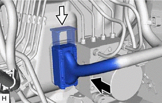

Connect the connector 
Lock the lock lever Connect the connector to the brake actuator assembly and lock the lock lever.
Note
-
Make sure that the connector is locked securely.
-
Make sure that the actuator connector can be connected smoothly. Do not allow water, oil or dirt to enter the connector.
-
-
-
INSTALL AIR CLEANER CASE SUB-ASSEMBLY (for 2AR-FE)
-
INSTALL AIR CLEANER CAP SUB-ASSEMBLY (for 2AR-FE)
-
INSTALL AIR CLEANER CASE SUB-ASSEMBLY (for 2GR-FE)
-
INSTALL AIR CLEANER CAP WITH AIR CLEANER HOSE (for 2GR-FE)
-
INSTALL V-BANK COVER SUB-ASSEMBLY (for 2GR-FE)
-
INSTALL BATTERY
for 2AR-FE: Click here
for 2GR-FE: Click here
-
INSTALL OUTER COWL TOP PANEL SUB-ASSEMBLY
for LHD: Click here
for RHD: Click here
-
INSTALL NO. 1 HEATER AIR DUCT SPLASH SHIELD SEAL
for LHD: Click here
for RHD: Click here
-
INSTALL NO. 2 HEATER AIR DUCT SPLASH SHIELD SEAL
for LHD: Click here
for RHD: Click here
-
INSTALL BRAKE MASTER CYLINDER RESERVOIR ASSEMBLY
for LHD: Click here
for RHD: Click here
-
INSTALL WINDSHIELD WIPER MOTOR AND LINK ASSEMBLY
for LHD: Click here
for RHD: Click here
-
INSPECT WASHER NOZZLE
-
CONNECT CABLE TO NEGATIVE BATTERY TERMINAL
Note
When disconnecting the cable, some systems need to be initialized after the cable is reconnected.
-
BLEED BRAKE SYSTEM
-
PERFORM YAW RATE AND ACCELERATION SENSOR ZERO POINT CALIBRATION AND STORE SYSTEM INFORMATION
-
PERFORM TEST MODE INSPECTION
-
INSPECT BRAKE ACTUATOR USING GTS
-
CHECK FOR AND CLEAR DTCS