UPPER INSTRUMENT PANEL INSTALLATION
CAUTION / NOTICE / HINT
Tech Tips
-
Use the same procedure for RHD and LHD vehicles.
-
The procedure listed below is for LHD vehicles.
-
A bolt without a torque specification is shown in the standard bolt chart.
PROCEDURE
-
INSTALL UPPER INSTRUMENT PANEL SUB-ASSEMBLY
-
for LHD:
-
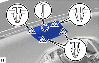
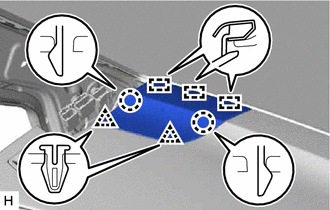
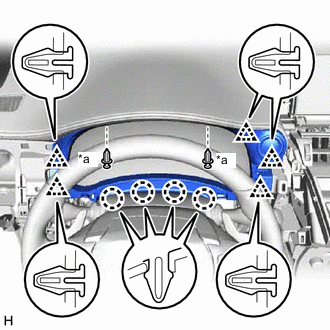
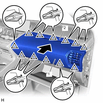
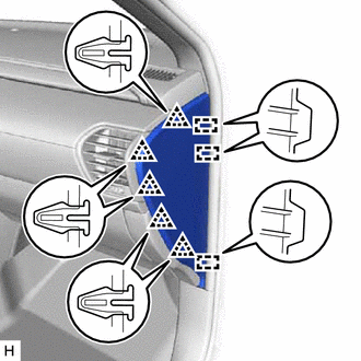
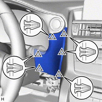
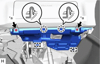
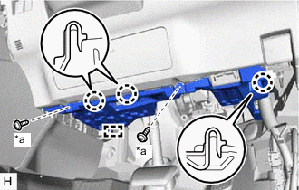
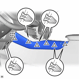
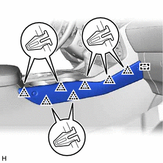
Attach the 5 guides and 7 clips to install the upper instrument panel sub-assembly.
-
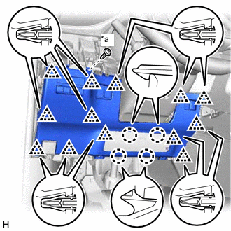
Install the 2 passenger airbag installation bolts <E>.
- Torque:
- 20 N*m { 204 kgf*cm, 15 ft.*lbf }
-
Install the 2 bolts <D> and screw <A> or <B>.
-
Connect the connectors.
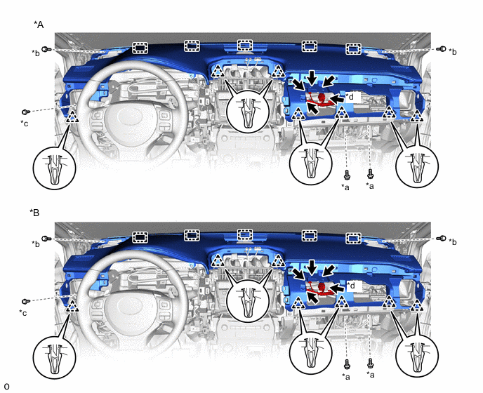
*A w/o Headup Display *B w/ Headup Display *a Passenger Airbag Installation Bolt <E> *b Bolt <D> *c Screw <A> or <B> *d Passenger Airbag Connector -
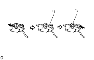
*1 Lock Slider *a Lock Position Connect the passenger airbag connector.
Note
When handling the passenger airbag connector, take care not to damage the airbag wire harness.
-
Check that the lock slider is in the lock position.
-
-
for RHD:
-
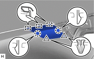
Attach the 5 guides and 7 clips to install the upper instrument panel sub-assembly.
-
Install the 2 passenger airbag installation bolts <E>.
- Torque:
- 20 N*m { 204 kgf*cm, 15 ft.*lbf }
-
Install the 2 bolts <D> and screw <A> or <B>.
-
Connect the connectors.
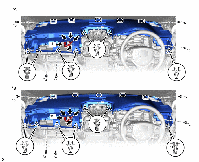
*A w/o Headup Display *B w/ Headup Display *a Passenger Airbag Installation Bolt <E> *b Bolt <D> *c Screw <A> or <B> *d Passenger Airbag Connector -
*1 Lock Slider *a Lock Position Connect the passenger airbag connector.
Note
When handling the passenger airbag connector, take care not to damage the airbag wire harness.
-
Check that the lock slider is in the lock position.
-
-
-
INSTALL FRONT NO. 3 SPEAKER ASSEMBLY
-
INSTALL FRONT NO. 2 SPEAKER ASSEMBLY
Tech Tips
Use the same procedure for both front No. 2 speaker assemblies.
Note
Do not touch the cone part of the front No. 2 speaker assembly.
-
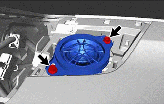
Connect the connector.
-
Install the front No. 2 speaker assembly with the 2 screws.
-
-
INSTALL NO. 1 SPEAKER OPENING COVER ASSEMBLY
-
Attach the claw and 4 clips to install the No. 1 speaker opening cover assembly.
-
-
INSTALL NO. 1 INSTRUMENT PANEL SPEAKER PANEL SUB-ASSEMBLY
-
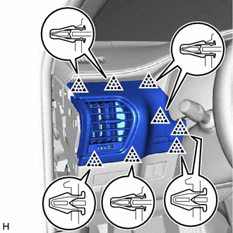
Attach the 3 guides, 2 claws and 2 clips to install the No. 1 instrument panel speaker panel sub-assembly.
-
-
INSTALL NO. 2 INSTRUMENT PANEL SPEAKER PANEL SUB-ASSEMBLY
-
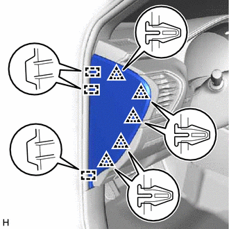
Attach the 3 guides, 2 claws and 2 clips to install the No. 2 instrument panel speaker panel sub-assembly.
-
-
INSTALL FRONT PILLAR GARNISH ASSEMBLY LH
-
INSTALL FRONT PILLAR GARNISH ASSEMBLY RH
-
CONNECT FRONT DOOR OPENING TRIM WEATHERSTRIP LH
-
Connect the front door opening trim weatherstrip LH.
-
-
CONNECT FRONT DOOR OPENING TRIM WEATHERSTRIP RH
-
Connect the front door opening trim weatherstrip RH.
-
-
INSTALL GLOVE COMPARTMENT DOOR ASSEMBLY
-
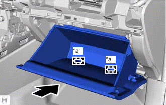
*a Hinge Attach the 2 hinges to install the glove compartment door assembly.
Note
When installing the glove compartment door assembly, make sure to install horizontally. Installing the glove compartment door assembly from above causes the hinges to become loose.
-
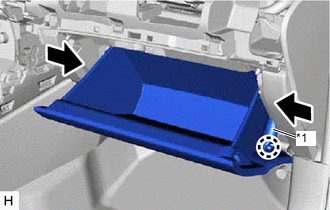
*1 Glove Compartment Door Stopper Sub-assembly While pushing in the sides of the glove compartment door assembly, attach the 2 stoppers.
-
Attach the claw to connect the glove compartment door stopper sub-assembly.
-
-
INSTALL COMBINATION METER ASSEMBLY
-
INSTALL INSTRUMENT CLUSTER FINISH PANEL SUB-ASSEMBLY
-
*a Clip <C> Connect the connector.
-
Attach the 5 clips and 4 claws to install the instrument cluster finish panel sub-assembly.
-
Install the 2 clips <C>.
-
-
INSTALL CENTER INSTRUMENT CLUSTER FINISH PANEL ASSEMBLY
-
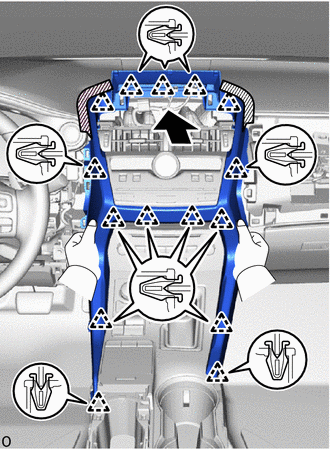
Attach the 15 clips to install the center instrument cluster finish panel assembly.
-
-
INSTALL MULTI-DISPLAY ASSEMBLY WITH BRACKET
-
INSTALL INSTRUMENT PANEL FINISH PLATE
-
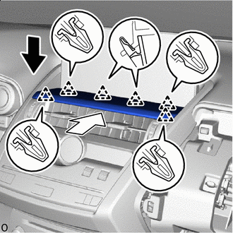

Install in this Direction (1) 
Install in this Direction (2) Down to the install direction (1) and set the instument panel finish plate.
-
Push to the install direction (2) and attach the 6 clips to install the instrument panel finish plate.
-
-
INSTALL NO. 2 INSTRUMENT PANEL SAFETY PAD SUB-ASSEMBLY
-
*1 No. 2 Instrument Panel Safety Pad Sub-assembly *2 No. 2 Instrument Cluster Finish Panel Garnish Attach the 12 clips to install the No. 2 instrument panel safety pad sub-assembly together with the No. 2 instrument cluster finish panel garnish.
-
-
INSTALL INSTRUMENT SIDE PANEL RH
-
Connect the connector.
-
Attach the 3 guides and 5 clips to install the instrument side panel RH.
-
-
INSTALL NO. 1 SWITCH HOLE BASE
-
Connect the connector.
-
Attach the 6 clips to install the No. 1 switch hole base.
-
-
INSTALL LOWER NO. 1 INSTRUMENT PANEL FINISH PANEL
-
*a Screw <A> or <B> Connect the connectors and attach the clamp.
-
Attach the 13 clips and 4 claws to install the lower No. 1 instrument panel finish panel.
-
Install the screw <A> or <B>.
-
-
INSTALL NO. 1 INSTRUMENT PANEL UNDER COVER SUB-ASSEMBLY
-
*a Screw <A> or <B> for LHD:
-
Connect the connector and attach the clamp.
-
Attach the 2 guides and 2 claws to install the No. 1 instrument panel under cover sub-assembly.
-
Install the screw <A> or <B>.
-
-
*a Screw <A> or <B> for RHD:
-
Connect the connector and attach the clamp.
-
Attach the guide and 3 claws to install the No. 1 instrument panel under cover sub-assembly.
-
Install the screw <A> or <B>.
-
-
-
INSTALL NO. 1 INSTRUMENT PANEL SAFETY PAD SUB-ASSEMBLY
-
Connect the connector.
-
Attach the 8 clips to install the No. 1 instrument panel safety pad sub-assembly.
-
-
INSTALL INSTRUMENT SIDE PANEL LH
-
Connect the connector.
-
Attach the 3 guides and 5 clips to install the instrument side panel LH.
-
-
INSTALL UPPER NO. 2 CONSOLE PANEL GARNISH
-
Attach the guide and 6 clips to install the upper No. 2 console panel garnish.
-
-
INSTALL UPPER NO. 1 CONSOLE PANEL GARNISH
-
Attach the guide and 7 clips to install the upper No. 1 console panel garnish.
-
-
INSTALL UPPER REAR CONSOLE PANEL
-
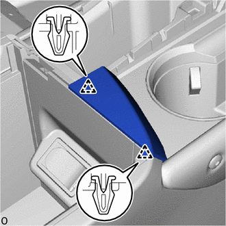
Attach the 2 clips to install the upper rear console panel.
-
-
INSTALL CONSOLE ARMREST ASSEMBLY
-
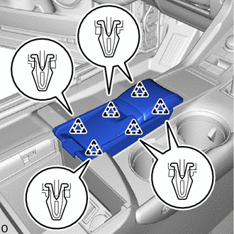
Attach the 6 clips to install the console armrest assembly.
-
Install the console armrest lid.
-
-
INSTALL COWL SIDE TRIM BOARD RH (for RHD)
-
INSTALL DOOR SCUFF PLATE ASSEMBLY RH (for RHD)
-
CONNECT CABLE TO NEGATIVE BATTERY TERMINAL
Note
When disconnecting the cable, some systems need to be initialized after the cable is reconnected.
-
ENABLE AUTOAWAY/RETURN FUNCTION (for Power Tilt and Power Telescopic Steering Column)
-
Restore the autoaway/return function setting to the previous condition by changing the customize parameter.
-
-
CHECK SRS WARNING LIGHT