RADIO ANTENNA CORD INSTALLATION
PROCEDURE
-
INSTALL NO. 4 ANTENNA CORD SUB-ASSEMBLY
-
Attach the 2 clamps and guide to install the No. 4 antenna cord sub-assembly.
-
Install the bolt and attach the 2 clamps to install the washer hose.
-
Connect each connector.
-
-
INSTALL NO. 2 ANTENNA CORD SUB-ASSEMBLY
-
When double-sided tape cannot be reused:
-
Remove the old double-sided tape
-
Remove the peeling paper on one side trying not to touch the adhesional surface, and attach new double-sided tape to the position indicated in the illustration
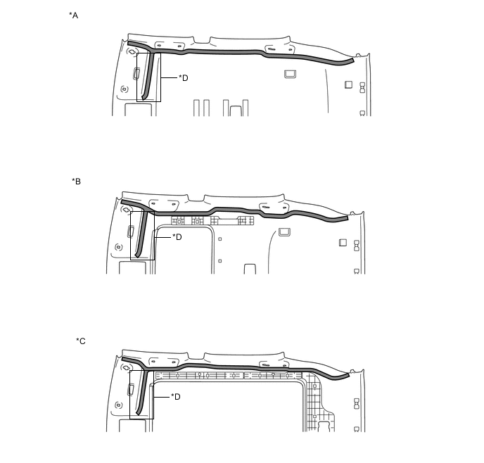
*A Normal roof *B Sliding roof *C Panoramic roof *D w/ Digital Audio Broadcasting, w/ Television Antenna 
Double-sided Tape - - Note
Attach securely so that the double-sided tape will not shift or peel off
-
Remove the peeling paper of the double-sided tape trying not to touch the adhesional surface.
-
-
Normal roof
-
Install the No. 2 antenna cord sub-assembly with the tape aligned to each marking of the roof headlining assembly as shown in the illustration.
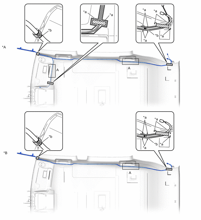
*A w/ Digital Audio Broadcasting, w/ Television Antenna *B w/o Digital Audio Broadcasting, w/o Television Antenna *a Marking *b Positioning Tape 
Tape - - Tech Tips
-
Secure the surplus of the No. 2 antenna cord sub-assembly at the <A> area of the illustration.
-
Secure the front part of the No. 2 antenna cord sub-assembly aligning the edge of the positioning tape and tab section of the roof headlining assembly.
-
Secure the rear part of the No. 2 antenna cord sub-assembly aligning the edge of the positioning tape and marking of the roof headlining assembly.
-
-
-
Sliding roof
-
Install the No. 2 antenna cord sub-assembly with the tape aligned to each marking of the roof headlining assembly as shown in the illustration
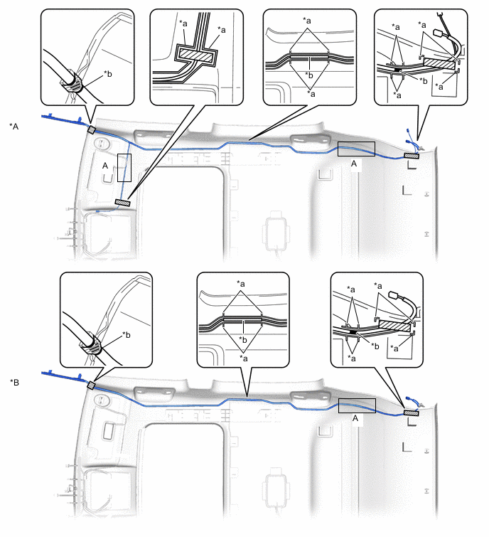
*A w/ Digital Audio Broadcasting, w/ Television Antenna *B w/o Digital Audio Broadcasting, w/o Television Antenna *a Marking *b Positioning Tape Tape - - Tech Tips
-
Secure the surplus of the No. 2 antenna cord sub-assembly at the <A> area of the illustration.
-
Secure the front part of the No. 2 antenna cord sub-assembly aligning the edge of the positioning tape and tab section of the roof headlining assembly.
-
Secure the rear part of the No. 2 antenna cord sub-assembly aligning the edge of the positioning tape and marking of the roof headlining assembly.
-
-
-
Panoramic moon roof
-
Install the No. 2 antenna cord sub-assembly with the tape aligned to each marking of the roof headlining assembly as shown in the illustration.
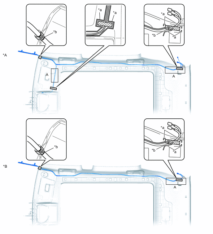
*A w/ Digital Audio Broadcasting, w/ Television Antenna *B w/o Digital Audio Broadcasting, w/o Television Antenna *a Marking *b Positioning Tape Tape - - Tech Tips
-
Secure the surplus of the No. 2 antenna cord sub-assembly at the <A> area of the illustration.
-
Secure the front part of the No. 2 antenna cord sub-assembly aligning the edge of the positioning tape and tab section of the roof headlining assembly.
-
Secure the rear part of the No. 2 antenna cord sub-assembly aligning the edge of the positioning tape and marking of the roof headlining assembly.
-
-
-
-
INSTALL ROOF HEADLINING ASSEMBLY
-
INSTALL NO. 1 ANTENNA CORD SUB-ASSEMBLY
-
for LHD:
-
Attach the 6 clamps and guide.
-
Install the No. 1 antenna cord sub-assembly with the bolt.
- Torque:
- 7.5 N*m { 76 kgf*cm, 66 in.*lbf }
-
Connect the connector.
-
-
for RHD:
-
Attach the 8 clamps and guide.
-
Install the No. 1 antenna cord sub-assembly with the bolt.
- Torque:
- 7.5 N*m { 76 kgf*cm, 66 in.*lbf }
-
Connect the connector.
-
-
-
INSTALL UPPER INSTRUMENT PANEL SUB-ASSEMBLY
-
CONNECT CABLE TO NEGATIVE BATTERY TERMINAL
Note
When disconnecting the cable, some systems need to be initialized after the cable is reconnected.
-
CHECK SRS WARNING LIGHT