FUEL PUMP(for High Pressure) INSTALLATION
PROCEDURE
-
SET FUEL PUMP ASSEMBLY
-
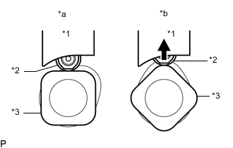
*1 Fuel Pump lifter guide *2 Fuel Pump lifter assembly *3 Camshaft *a Correct *b Incorrect Turn the crankshaft pulley so that the flat surface of the cam lobe faces upward from the fuel pump assembly installation hole of the cylinder head cover sub-assembly.
Tech Tips
By performing the above procedure, the cam lobe nose does not push up the drive face of the fuel pump assembly when installing the fuel pump assembly.
-
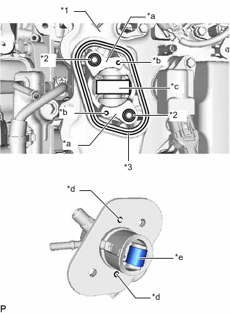
*1 Cylinder Head Cover Sub-assembly *2 O-ring *3 Gasket *a Pump Housing *b Knock Pin *c Pump Drive Cam (Engine Oil Application Point) *d Positioning Knock Hole *e Pump Lifter (Engine Oil Application Point) Apply 30 cc (1.8 cu in.) of engine oil to the pump drive cam.
-
Apply engine oil to the fuel pump lifter assembly.
-
Apply engine oil to the 2 new O-rings and install it to the pump housing.
-
Install a new gasket to the cylinder head cover sub-assembly.
-
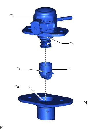
*1 Fuel Pump Assembly *2 O-ring *3 Fuel Pump Lifter Assembly *4 Fuel Pump Lifter Guide *a Engine Oil Application Point Apply engine oil to a new O-ring and install it to the fuel pump assembly.
-
Apply engine oil to the inside of the fuel pump lifter guide and the outside of the fuel pump lifter assembly.
-
Install the fuel pump lifter assembly to the fuel pump lifter guide.
-
Set the fuel pump assembly on the cylinder head cover sub-assembly.
-
Temporarily install the fuel pump assembly with the 2 bolts, leaving some allowance for left and right movement.
-
-
TEMPORARILY INSTALL NO. 1 FUEL PIPE SUB-ASSEMBLY
Note
Do not damage the seals of the union nuts of the No. 1 fuel pipe sub-assembly when installing.
-
Temporarily install the union nuts on the fuel pump assembly side of the No. 1 fuel pipe sub-assembly until they are completely tightened.
-
Temporarily install the union nuts on the fuel delivery pipe sub-assembly side of the No. 1 fuel pipe sub-assembly until they are completely tightened.
-
-
INSTALL FUEL PUMP ASSEMBLY
Tech Tips
Perform "Inspection After Repair" after replacing the fuel pump assembly.
-
w/ Canister Pump Module:
-
w/o Canister Pump Module:
-
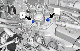
Install the fuel pump assembly by uniformly tightening the 2 bolts in several steps in the order shown in the illustration.
- Torque:
- 15 N*m { 153 kgf*cm, 11 ft.*lbf }
-
Tighten the 2 bolts in the order shown in the illustration again.
- Torque:
- 30 N*m { 306 kgf*cm, 22 ft.*lbf }
-
Connect the connector to the fuel pump assembly.
-
-
TIGHTEN NO. 1 FUEL PIPE SUB-ASSEMBLY
-
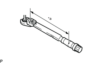
*a Torque Wrench Fulcrum Length Using a 17 mm union nut wrench, tighten the union nuts on the fuel delivery pipe sub-assembly side of the No. 1 fuel pipe sub-assembly.
- Torque:
- Specified tightening torque
- 35 N*m { 357 kgf*cm, 26 ft.*lbf }
Tech Tips
-
Calculate the torque wrench reading when changing the fulcrum length of the torque wrench.
-
When using a union nut wrench (fulcrum length of 30 mm (1.18 in.)) + torque wrench (fulcrum length of 180 mm (7.09 in.)): 30 N*m (306 kgf*cm, 22 ft.*lbf)
-
*a Torque Wrench Fulcrum Length Using a 17 mm union nut wrench, tighten the union nuts on the fuel pump assembly side of the No. 1 fuel pipe sub-assembly.
- Torque:
- Specified tightening torque
- 35 N*m { 357 kgf*cm, 26 ft.*lbf }
Tech Tips
-
Calculate the torque wrench reading when changing the fulcrum length of the torque wrench.
-
When using a union nut wrench (fulcrum length of 30 mm (1.18 in.)) + torque wrench (fulcrum length of 180 mm (7.09 in.)): 30 N*m (306 kgf*cm, 22 ft.*lbf)
-
-
CONNECT FUEL TUBE SUB-ASSEMBLY
-
Connect the fuel tube sub-assembly to the fuel pump assembly.
-
-
INSTALL BRACKET
-
Using an E8 "TORX" socket wrench, install the stud bolt to the cylinder head sub-assembly.
- Torque:
- 9.0 N*m { 92 kgf*cm, 80 in.*lbf }
-
Install the bracket to the cylinder head sub-assembly with the bolt.
- Torque:
- 21 N*m { 214 kgf*cm, 15 ft.*lbf }
-
-
INSTALL FUEL PUMP PROTECTOR
-
Install the fuel pump protector to the bracket and cylinder head sub-assembly with the bolt and nut.
- Torque:
- 21 N*m { 214 kgf*cm, 15 ft.*lbf }
-
-
INSTALL INTAKE MANIFOLD
-
INSPECT FOR FUEL LEAK
-
PERFORM INITIALIZATION
-
Perform "Inspection After Repair" after replacing the fuel pump assembly.
-
w/ Canister Pump Module:
-
w/o Canister Pump Module:
-
-