SFI SYSTEM(w/ Canister Pump Module), Diagnostic DTC:P04DB00
| DTC Code | DTC Name |
|---|---|
| P04DB00 | Crankcase Ventilation System Disconnected |
DESCRIPTION
In the PCV system for a turbocharged engine, the blow-by gas is drawn into the intake pipe due to the intake vacuum via the PCV valve in the natural aspiration range, and blow-by gas forcibly flows through the intake pipe via the ejector to recirculate blow-by in all driving ranges in the turbocharged intake range.
| DTC No. | Detection Item | DTC Detection Condition | Trouble Area | MIL | Memory | Note |
|---|---|---|---|---|---|---|
| P04DB00 | Crankcase Ventilation System Disconnected | PCV system air leakage or suction is detected (2 trip detection logic). |
|
Comes on | DTC stored | SAE: P04DB |
MONITOR DESCRIPTION
The ECM monitors for PCV system air leakage and suction.
If air leakage or suction occurs, air is sucked in by the intake vacuum during idling causing the air-fuel ratio to become lean and adjustment to the rich side to occur, and when air leaks due to boost pressure during turbocharging, the air-fuel ratio becomes rich and is adjusted to the lean side.
When the air fuel ratio is adjusted to the rich side during idling and adjusted to the lean side during turbocharging, it is determined that there is air leakage or suction in the PCV system.
If the air-fuel ratio calibration amount for the difference in air-fuel ratio when idling and when turbocharging exceeds the threshold, the ECM illuminates the MIL and stores a DTC. (2 trip detection logic)
MONITOR STRATEGY
| Required Sensors/Components | Air fuel ratio sensor Mass air flow meter sub-assembly Crankshaft position sensor No. 2 turbo pressure sensor |
| Frequency of Operation | Once per driving cycle |
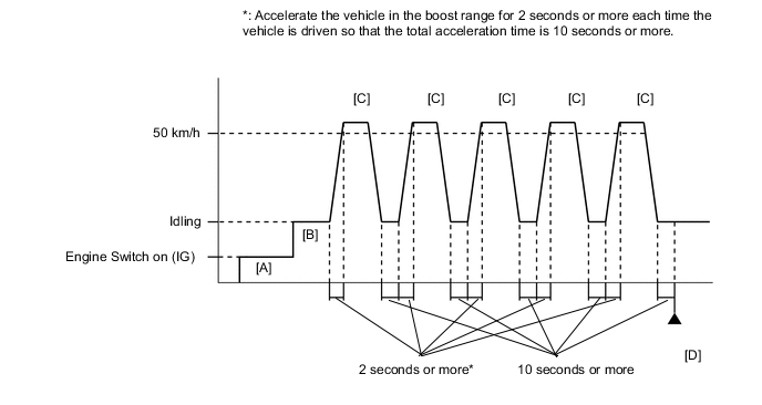
CONFIRMATION DRIVING PATTERN
-
Connect the GTS to the DLC3.
-
Turn the engine switch on (IG) and turn the GTS on
-
Clear the DTCs (even if no DTCs are stored, perform the clear DTC procedure).
-
Turn the engine switch off and wait for at least 30 seconds.
-
Turn the engine switch on (IG) and turn the GTS on [A].
-
Start the engine and warm it up until the engine coolant temperature is 75°C (167°F) or higher with all the accessories switched off [B].
-
Accelerate the vehicle to 50 km/h (31 mph) or more, and then idle the engine for 10 seconds or more [C].
CAUTION:
When performing the confirmation driving pattern, obey all speed limits and traffic laws.
Tech Tips
Make sure to accelerate the vehicle in the boost range for 2 seconds or more.
-
Repeat step [C] 5 times or more.
Tech Tips
Make sure to accelerate the vehicle in the boost range for a total of 10 seconds or more.
-
Enter the following menus: Powertrain / Engine / Trouble Codes [D].
-
Read the pending DTCs.
Tech Tips
-
If a pending DTC is output, the system is malfunctioning.
-
If a pending DTC is not output, perform the following procedure.
-
-
Enter the following menus: Powertrain / Engine / Utility / All Readiness.
-
Input the DTC: P04DB00.
-
Check the DTC judgment result.
GTS Display Description NORMAL
-
DTC judgment completed
-
System normal
ABNORMAL
-
DTC judgment completed
-
System abnormal
INCOMPLETE
-
DTC judgment not completed
-
Perform driving pattern after confirming DTC enabling conditions
N/A
-
Unable to perform DTC judgment
-
Number of DTCs which do not fulfill DTC preconditions has reached ECU memory limit
Tech Tips
-
If the judgment result shows NORMAL, the system is normal.
-
If the judgment result shows ABNORMAL, the system has a malfunction.
-
If the judgment result shows INCOMPLETE or N/A, perform steps [C] and [D] again.
-
WIRING DIAGRAM
Refer to DTC P010012 for the mass air flow meter sub-assembly circuit.
Refer to DTC P003012 for air fuel ratio sensor circuit.
CAUTION / NOTICE / HINT
Tech Tips
Read freeze frame data using the GTS. The ECM records vehicle and driving condition information as freeze frame data the moment a DTC is stored. When troubleshooting, freeze frame data can help determine if the vehicle was moving or stationary, if the engine was warmed up or not, if the air fuel ratio was lean or rich, and other data from the time the malfunction occurred.
PROCEDURE
-
CHECK ANY OTHER DTCS OUTPUT (IN ADDITION TO DTC P04DB00)
-
Connect the GTS to the DLC3
-
Turn the engine switch on (IG).
-
Turn the GTS on.
-
Enter the following menus: Powertrain / Engine / Trouble Codes.
-
Read the DTCs.
Powertrain > Engine > Trouble CodesResult Result Proceed to DTC P04DB00 is output A DTC P04DB00 and P017100 and/or P017200 are output DTC P04DB00 and other DTCs are output B Tech Tips
-
If DTC P04DB00 and P017100 and/or P017200 are output simultaneously, troubleshoot for DTC P04DB00 first.
-
If any DTCs other than P04DB00 are output, troubleshoot those DTCs first.
-
B 
GO TO DTC CHART Click here
A 
-
-
CHECK PCV HOSE CONNECTIONS
-
Check the PCV hose connections.
OK PCV valve and hose are connected correctly and are not damaged. 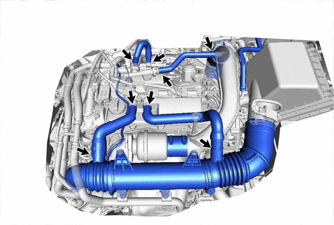
Result Proceed to OK NG
NG 
REPAIR OR REPLACE PCV HOSE Click here
OK
-
-
CHECK INTAKE SYSTEM
-
Check the intake system for vacuum leaks.
OK No leaks in intake system. Result Proceed to OK NG
NG
REPAIR OR REPLACE INTAKE SYSTEM Click here
OK
-
-
PERFORM ACTIVE TEST USING GTS (CONTROL THE INJECTION VOLUME FOR A/F SENSOR)
-
Connect the GTS to the DLC3.
-
Start the engine.
-
Turn the GTS on.
-
Warm up the engine and run the engine at an engine speed of 2500 rpm for approximately 90 seconds.
-
Enter the following menus: Powertrain / Engine / Active Test / Control the Injection Volume for A/F Sensor / Data List / A/F (O2) Sensor Voltage B1S1 and O2 Sensor Voltage B1S2.
Powertrain > Engine > Active TestActive Test Display Control the Injection Volume for A/F Sensor Data List Display A/F (O2) Sensor Voltage B1S1 O2 Sensor Voltage B1S2 -
Perform the Control the Injection Volume for A/F Sensor operation with the engine idling (press the RIGHT or LEFT button to change the fuel injection volume).
-
Monitor the voltage outputs of the air fuel ratio sensor and the heated oxygen sensor (A/F (O2) Sensor Voltage B1S1 and O2 Sensor Voltage B1S2) displayed on the GTS.
Tech Tips
-
Change the injection volume operation lowers the fuel injection volume by 12.5% or increases the injection volume by 12.5%.
-
The air fuel ratio sensor has an output delay of a few seconds and the heated oxygen sensor has a maximum output delay of approximately 20 seconds.
-
If the sensor output voltage does not change (almost no reaction) while performing the Active Test, the sensor may be malfunctioning.
Standard GTS Display (Sensor) Injection Volume Status Voltage A/F (O2) Sensor Voltage B1S1
(Air fuel ratio)
12.5% Rich Below 3.1 V -12.5% Lean Higher than 3.4 V O2 Sensor Voltage B1S2
(Heated oxygen)
12.5% Rich Higher than 0.55 V -12.5% Lean Below 0.4 V Result Status A/F (O2) Sensor Voltage B1S1 Status O2 Sensor Voltage B1S2 Air Fuel Ratio Condition and Air Fuel Ratio Sensor Condition Suspected Trouble Area Proceed to Lean/Rich Lean/Rich Normal - A Lean Lean Actual air fuel ratio lean
-
PCV valve and hose
-
PCV hose connections
-
Gas leak from exhaust system
-
Intake system
-
Mass air flow meter sub-assembly
-
Engine coolant temperature sensor
Rich Rich Actual air fuel ratio rich
-
Gas leak from exhaust system
-
Ignition system
-
Mass air flow meter sub-assembly
-
Engine coolant temperature sensor
Lean Lean/Rich Air fuel ratio sensor malfunction
-
Air fuel ratio sensor
B Rich Lean/Rich Air fuel ratio sensor malfunction
-
Air fuel ratio sensor
-
Lean: During Control the Injection Volume for A/F Sensor, the air fuel ratio sensor output voltage (A/F (O2) Sensor Voltage B1S1) is consistently higher than 3.4 V, and the heated oxygen sensor output voltage (O2 Sensor Voltage B1S2) is consistently below 0.4 V.
-
Rich: During Control the Injection Volume for A/F Sensor, the A/F (O2) Sensor Voltage B1S1 is consistently below 3.1 V, and the O2 Sensor Voltage B1S2 is consistently higher than 0.55 V.
-
Lean/Rich: During Control the Injection Volume for A/F Sensor of the Active Test, the output voltage of the heated oxygen sensor alternates correctly.
Tech Tips
Refer to "Data List / Active Test" [A/F (O2) Sensor Voltage B1S1 and O2 Sensor Voltage B1S2].
-
B
INSPECT AIR FUEL RATIO SENSOR (HEATER RESISTANCE) Click here
A
-
-
READ VALUE USING GTS (COOLANT TEMPERATURE)
-
Connect the GTS to the DLC3.
-
Turn the engine switch on (IG).
-
Turn the GTS on.
-
Enter the following menus: Powertrain / Engine / Data List / Coolant Temperature.
Powertrain > Engine > Data ListTester Display Coolant Temperature -
Read the Data List twice, when the engine is both cold and warmed up.
Standard GTS Display Condition Specified Condition Coolant Temperature Cold engine Same as ambient air temperature Warm engine Between 75 and 100°C (167 and 212°F) Tech Tips
Perform "Inspection After Repair" after replacing the engine coolant temperature sensor.
Result Proceed to OK NG
NG
REPLACE ENGINE COOLANT TEMPERATURE SENSOR Click here
OK
-
-
READ VALUE USING GTS (MASS AIR FLOW SENSOR)
-
Connect the GTS to the DLC3.
-
Start the engine.
-
Turn the GTS on.
-
Enter the following menus: Powertrain / Engine / Data List / Mass Air Flow Sensor, Coolant Temperature and Engine Speed.
Powertrain > Engine > Data ListTester Display Engine Speed Mass Air Flow Sensor Coolant Temperature -
Allow the engine to idle until Coolant Temperature reaches 75°C (167°F) or higher.
-
Read Mass Air Flow Sensor with the engine speed at 3000 rpm.
Standard GTS Display Condition Specified Condition Mass Air Flow Sensor Shift lever position: N
A/C: Off
Engine Speed: 3000 rpm
Between 6.0 gm/sec and 18.0 gm/sec Result Proceed to OK NG
NG
GO TO STEP 12 Click here
OK
-
-
CHECK FOR EXHAUST GAS LEAK
-
Check for exhaust gas leaks.
OK No gas leaks. Tech Tips
Perform "Inspection After Repair" after repairing or replacing the exhaust system.
Result Proceed to OK NG
OK
GO TO STEP 11 Click here
NG
REPAIR OR REPLACE EXHAUST SYSTEM
-
-
INSPECT AIR FUEL RATIO SENSOR (HEATER RESISTANCE)
-
Inspect the air fuel ratio sensor.
Result Proceed to OK NG
NG
REPLACE AIR FUEL RATIO SENSOR Click here
OK
-
-
CHECK HARNESS AND CONNECTOR (AIR FUEL RATIO SENSOR - ECM)
-
Disconnect the air fuel ratio sensor connector.
-
Disconnect the ECM connector.
-
Measure the resistance according to the value(s) in the table below.
Standard Resistance Tester Connection Condition Specified Condition C5-1 (HA1A) - C20-19 (HA1A) Always Below 1 Ω C5-3 (A1A+) - C20-131 (A1A+) Always Below 1 Ω C5-4 (A1A-) - C20-132 (A1A-) Always Below 1 Ω C5-1 (HA1A) or C20-19 (HA1A) - Body ground and other terminals Always 10 kΩ or higher C5-3 (A1A+) or C20-131 (A1A+) - Body ground and other terminals Always 10 kΩ or higher C5-4 (A1A-) or C20-132 (A1A-) - Body ground and other terminals Always 10 kΩ or higher Result Proceed to OK NG
NG
REPAIR OR REPLACE HARNESS OR CONNECTOR
OK
-
-
REPLACE AIR FUEL RATIO SENSOR
-
Replace the air fuel ratio sensor.
Result Proceed to NEXT
NEXT
-
-
CHECK WHETHER DTC OUTPUT RECURS (DTC P04DB00)
-
Connect the GTS to the DLC3.
-
Turn the engine switch on (IG).
-
Turn the GTS on.
-
Clear the DTCs.
Powertrain > Engine > Clear DTCs -
Turn the engine switch off and wait for at least 30 seconds.
-
Start the engine and warm it up.
-
Turn the GTS on.
-
Drive the vehicle in accordance with the driving pattern described in Confirmation Driving Pattern.
-
Enter the following menus: Powertrain / Engine / Utility / All Readiness.
Powertrain > Engine > UtilityTester Display All Readiness -
Input the DTC: P04DB00.
-
Check the DTC judgment result.
Result Result Proceed to ABNORMAL
(DTC P04DB00 is output)
A NORMAL
(DTCs are not output)
B
B
END
A
-
-
CHECK HARNESS AND CONNECTOR (MASS AIR FLOW METER SUB-ASSEMBLY CONNECTOR CONNECTION)
-
Check the connection and terminal contact pressure of connectors and wire harnesses between the mass air flow meter sub-assembly and ECM.
Tech Tips
Repair any problems.
Result Proceed to NEXT
NEXT
-
-
CHECK WHETHER DTC OUTPUT RECURS (DTC P04DB00)
-
Connect the GTS to the DLC3.
-
Turn the engine switch on (IG).
-
Turn the GTS on.
-
Clear the DTCs.
Powertrain > Engine > Clear DTCs -
Turn the engine switch off and wait for at least 30 seconds.
-
Start the engine and warm it up.
-
Turn the GTS on.
-
Drive the vehicle in accordance with the driving pattern described in Confirmation Driving Pattern.
-
Enter the following menus: Powertrain / Engine / Utility / All Readiness.
Powertrain > Engine > UtilityTester Display All Readiness -
Input the DTC: P04DB00.
-
Check the DTC judgment result.
Result Result Proceed to ABNORMAL
(DTC P04DB00 is output)
A NORMAL
(DTCs are not output)
B
B
END
A
-
-
CHECK HARNESS AND CONNECTOR (MASS AIR FLOW METER SUB-ASSEMBLY - ECM)
-
Disconnect the mass air flow meter sub-assembly connector.
-
Disconnect the ECM connector.
-
Measure the resistance according to the value(s) in the table below.
Standard Resistance Tester Connection Condition Specified Condition C1-5 (VG) - C20-92 (VG) Always Below 1 Ω C1-4 (E2G) - C20-91 (E2G) Always Below 1 Ω C1-5 (VG) or C20-92 (VG) - Body ground and other terminals Always 10 kΩ or higher Result Proceed to OK NG
NG
REPAIR OR REPLACE HARNESS OR CONNECTOR
OK
-
-
REPLACE MASS AIR FLOW METER SUB-ASSEMBLY
-
Replace the mass air flow meter sub-assembly.
Tech Tips
-
If the result of the inspection performed in step 6 indicated no problem, proceed to the next step without replacing the mass air flow meter sub-assembly.
-
Perform "Inspection After Repair" after replacing the mass air flow meter sub-assembly.
Result Proceed to NEXT -
NEXT
-
-
CHECK WHETHER DTC OUTPUT RECURS (DTC P04DB00)
-
Connect the GTS to the DLC3.
-
Turn the engine switch on (IG).
-
Turn the GTS on.
-
Clear the DTCs.
Powertrain > Engine > Clear DTCs -
Turn the engine switch off and wait for at least 30 seconds.
-
Start the engine and warm it up.
-
Turn the GTS on.
-
Drive the vehicle in accordance with the driving pattern described in Confirmation Driving Pattern.
-
Enter the following menus: Powertrain / Engine / Utility / All Readiness.
Powertrain > Engine > UtilityTester Display All Readiness -
Input the DTC: P04DB00.
-
Check the DTC judgment result.
Result Result Proceed to ABNORMAL
(DTC P04DB00 is output)
A NORMAL
(DTCs are not output)
B
A
REPLACE ECM Click here
B
END
-
-
REPAIR OR REPLACE INTAKE SYSTEM
-
Repair or replace the intake system.
Tech Tips
Perform "Inspection After Repair" after repairing or replacing the intake system.
Result Proceed to NEXT
NEXT
GO TO STEP 19 Click here
-
-
REPAIR OR REPLACE PCV HOSE
-
Repair or replace the PCV hose.
Result Proceed to NEXT
NEXT
-
-
CHECK WHETHER DTC OUTPUT RECURS (DTC P04DB00)
-
Connect the GTS to the DLC3.
-
Turn the engine switch on (IG).
-
Turn the GTS on.
-
Clear the DTCs.
Powertrain > Engine > Clear DTCs -
Turn the engine switch off and wait for at least 30 seconds.
-
Start the engine and warm it up.
-
Turn the GTS on.
-
Drive the vehicle in accordance with the driving pattern described in Confirmation Driving Pattern.
-
Enter the following menus: Powertrain / Engine / Utility / All Readiness.
Powertrain > Engine > UtilityTester Display All Readiness -
Input the DTC: P04DB00.
-
Check the DTC judgment result.
GTS Display Description NORMAL
-
DTC judgment completed
-
System normal
ABNORMAL
-
DTC judgment completed
-
System abnormal
INCOMPLETE
-
DTC judgment not completed
-
Perform driving pattern after confirming DTC enabling conditions
N/A
-
Unable to perform DTC judgment
-
Number of DTCs which do not fulfill DTC preconditions has reached ECU memory limit
Result Proceed to NEXT -
NEXT
END
-