CAUTION / NOTICE / HINT
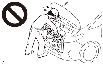
To prevent injury due to contact with an operating V-ribbed belt or cooling fan, keep your hands and clothing away from the V-ribbed belt and cooling fans when working in the engine compartment with the engine running or the engine switch on (IG).
PROCEDURE
- Click here
INSPECT ENGINE COOLANT
- Click here
INSPECT ENGINE OIL
- Click here
INSPECT BATTERY CONDITION
- Click here
INSPECT SPARK PLUG
- Click here
INSPECT AIR CLEANER FILTER ELEMENT SUB-ASSEMBLY
-
Remove the air cleaner filter element sub-assembly.
-
Visually check that the air cleaner filter element sub-assembly is not damaged or excessively oily. If necessary, replace the air cleaner filter element sub-assembly.
Tip:
-
If there is any dirt or clogs in the air cleaner filter element sub-assembly, clean it with compressed air.
-
If any dirt or clogs remain even after cleaning the air cleaner filter element sub-assembly with compressed air, replace it.
-
-
Install the air cleaner filter element sub-assembly.
-
- Click here
INSPECT V-RIBBED BELT
- Click here
INSPECT V-RIBBED BELT TENSIONER ASSEMBLY
-
Remove the V-ribbed belt.
-
Turn the V-ribbed belt tensioner assembly clockwise and counterclockwise and check that it turns smoothly and does not catch.
Tip:If the V-ribbed belt tensioner assembly does not turn smoothly or catches, replace the V-ribbed belt tensioner assembly.
-
Install the V-ribbed belt.
-
- Click here
INSPECT VALVE LASH ADJUSTER ASSEMBLY NOISE
-
Rev up the engine several times. Check that the engine does not emit unusual noises.
-
If unusual noises occur, warm up the engine and idle it for 30 minutes or more, then perform the inspection.
Tip:If any defects or problems are found during the inspection, perform valve lash adjuster assembly inspection.
-
- Click here
INSPECT IGNITION TIMING
-
Warm up and stop the engine.
-
When using the GTS:
-
Connect the GTS to the DLC3.
-
Start the engine and run it at idle.
-
Turn the GTS on.
-
Enter the following menus: Powertrain / Engine / Data List / IGN Advance.
- Powertrain > Engine > Data List
Tester Display IGN Advance -
-
-
-
Standard Ignition Timing 5 to 20° BTDC at idle Note:
-
Check the ignition timing with the cooling fans off.
-
Turn off all electrical systems and the A/C.
-
When checking the ignition timing, the transaxle should be in neutral or park.
- Powertrain > Engine > Data List
-
Enter the following menus: Powertrain / Engine / Active Test / Connect the TC and TE1 / ON.
- Powertrain > Engine > Active Test
Active Test Display Connect the TC and TE1 Data List Display IGN Advance -
-
-
-
- Powertrain > Engine > Active Test
-
Monitor IGN Advance of the Data List.
Standard Ignition Timing 8 to 12° BTDC at idle -
Enter the following menus: Powertrain / Engine / Active Test / Connect the TC and TE1 / OFF.
-
Check that the ignition timing advances immediately when the engine speed is increased.
-
-
When not using the GTS:
-
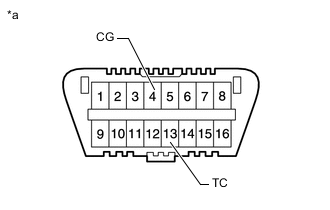
*a DLC3 Using SST, connect terminals 13 (TC) and 4 (CG) of the DLC3.
09843-18040 Note:
-
Confirm the terminal numbers before connecting them. Connecting the wrong terminals may damage electrical components.
-
Check the ignition timing with the cooling fans off.
-
Turn off all electrical systems and the A/C.
-
When checking the ignition timing, the transaxle should be in neutral or park.
-
-
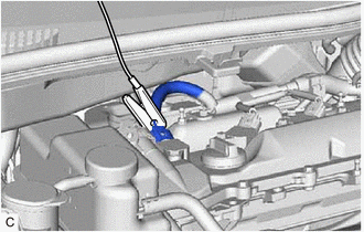
Connect the clip of a timing light to the ignition coil wire for the No. 1 cylinder.
Note:Use a timing light that detects primary signals.
-
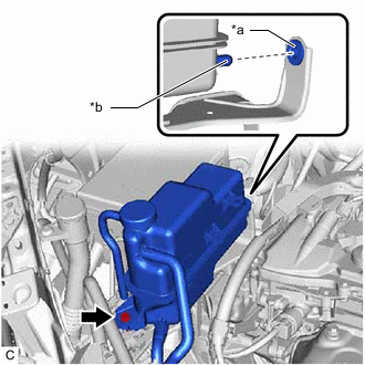
*a Grommet *b Protrusion Remove the bolt and separate the radiator reserve tank assembly from the radiator reserve tank bracket.
Note:Secure the radiator reserve tank assembly with a string.
-
Remove the radiator reserve tank bracket.
-
Start the engine and run it at idle.
-
Check the ignition timing at idle.
Standard Ignition Timing 8 to 12° BTDC at idle -
Disconnect terminals 13 (TC) and 4 (CG) of the DLC3.
-
Check the ignition timing at idle.
Standard Ignition Timing 5 to 20° BTDC at idle -
Confirm that the ignition timing advances immediately when the engine speed is increased.
-
Install the radiator reserve tank bracket.
-
Install the radiator reserve tank assembly to the radiator reserve tank bracket with the bolt.
12 N*m 122 kgf*cm 9 ft.*lbf Note:Insert the protrusion of the radiator reserve tank assembly into the grommet of the radiator reserve tank bracket.
-
Disconnect the clip of the timing light from the ignition coil wire for the No. 1 cylinder.
-
-
- Click here
INSPECT ENGINE IDLE SPEED
-
Warm up and stop the engine.
-
When using the GTS:
-
Connect the GTS to the DLC3.
-
Start the engine and run it at idle.
-
Turn the GTS on.
-
Enter the following menus: Powertrain / Engine / Data List / Engine Speed.
- Powertrain > Engine > Data List
Tester Display Engine Speed -
-
-
-
- Powertrain > Engine > Data List
-
Read the value displayed on the tester.
Standard Idle Speed 700 to 800 rpm Note:
-
Check the engine idle speed with the cooling fans off.
-
Turn off all electrical systems and the A/C.
-
When checking the engine idle speed, the transaxle should be in neutral or park.
-
-
-
When not using the GTS:
-
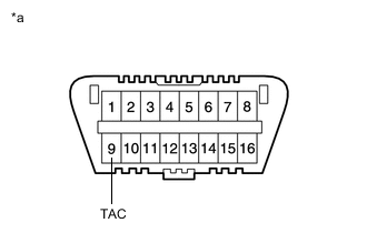
*a DLC3 Using SST, connect a tachometer probe to terminal 9 (TAC) of the DLC3.
09843-18030 Note:Be sure to connect the tachometer probe to the correct terminal. Connecting the wrong terminals can cause damage to electrical components.
-
Start the engine and run it at idle.
-
Inspect the engine idle speed.
Standard Idle Speed 700 to 800 rpm Note:
-
Check the engine idle speed with the cooling fans off.
-
Turn off all electrical systems and the A/C.
-
When checking the engine idle speed, the transaxle should be in neutral or park.
-
-
Disconnect the tachometer probe from terminal 9 (TAC) of the DLC3.
-
-
- Click here
INSPECT COMPRESSION
Note:Keep the spark plug holes free of foreign matter when measuring the compression pressure.
-
Warm up and stop the engine.
-
Check for DTCs.
-
Remove the 4 spark plugs.
-
Disconnect the 4 fuel injector connectors.
-
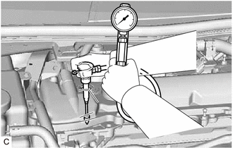
Check the cylinder compression pressure.
-
Insert a compression gauge into the spark plug hole.
-
Fully open the throttle.
-
While cranking the engine, measure the compression pressure.
Standard Compression Pressure 1450 kPa (14.8 kgf/cm2, 210 psi) Minimum Compression Pressure 980 kPa (10.0 kgf/cm2, 142 psi) Pressure Difference between Each Cylinder 200 kPa (2.0 kgf/cm2, 29 psi) or less Note:
-
Always use a fully charged battery to obtain an engine speed of 250 rpm or more.
-
Inspect all cylinders in the same way.
-
Measure the compression pressure as quickly as possible.
-
-
If the cylinder compression pressure is low, pour a small amount of engine oil into the cylinder through the spark plug hole and inspect it again.
Tip:
-
If adding oil increases the compression pressure, the piston rings and/or cylinder bore may be worn or damaged.
-
If the compression pressure stays low, a valve may be stuck or seated improperly, or there may be leaks in the cylinder head gasket.
-
-
-
Connect the 4 fuel injector connectors.
-
Install the 4 spark plugs.
-
Clear the DTCs.
Note:After the inspection, clear the DTCs, check for DTCs again and make sure the normal system code is output.
-
- Click here
INSPECT CO/HC
Tip:This check determines whether or not the idle CO/HC complies with regulations.
-
Start the engine.
-
Run the engine at 2500 rpm for approximately 180 seconds.
-
Insert a CO/HC meter testing probe at least 40 cm (1.31 ft.) into the tailpipe during idle.
-
Immediately check the CO/HC concentration during idle and when the engine is running at 2500 rpm.
Tip:When performing a 2 mode (with the engine idling/running at 2500 rpm) test, the measurement procedures are determined by applicable local regulations.
If the CO/HC concentration does not comply with the regulations, perform troubleshooting in the order given below.
-
Check for DTCs.
-
See the following table for possible causes, then inspect the applicable parts and repair them if necessary.
CO HC Problem Cause Normal High Rough idle
-
Faulty ignition:
-
-
Incorrect valve timing
-
Fouled, shorted or improperly gapped spark plugs
-
-
Incorrect valve clearance (valve lash adjuster assembly)
-
Leaks in intake or exhaust valves
-
Leaks in cylinders
Low High Rough idle (Fluctuating HC reading)
-
Vacuum leaks:
-
-
PCV hoses
-
Intake manifold
-
Throttle with motor body assembly
-
-
Lean mixture causing misfire
High High Rough idle (Black smoke from exhaust)
-
Restricted air cleaner filter element sub-assembly
-
Plugged PCV valve
-
Faulty SFI systems:
-
-
Fuel pressure regulator assembly
-
Engine coolant temperature sensor
-
Mass air flow meter sub-assembly
-
ECM
-
Fuel injector assemblies
-
Throttle position sensor (built into throttle with motor body assembly)
-
-
-
-