PROCEDURE
- Click here
INSTALL POWER STEERING LINK ASSEMBLY
-
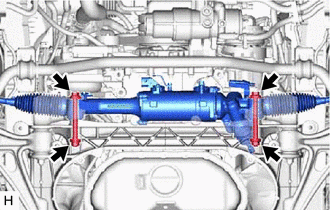
Install the power steering link assembly with the 2 bolts, 2 washers and 2 nuts.
117.6 N*m 1199 kgf*cm 87 ft.*lbf -
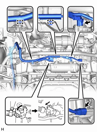
Connect the 2 wire harness clamps to the power steering link assembly.
-
Connect the 3 wire harness connectors to the power steering link assembly.
Tip:When connecting the connector with lock lever, return the lock lever to its original position and securely push in the lock of the lock lever as shown in the illustration.
-
- Click here
CONNECT TIE ROD ASSEMBLY LH
-
Connect the tie rod assembly LH to the steering knuckle with the nut.
65 N*m 663 kgf*cm 48 ft.*lbf Note:Prevent oil from adhering to the threaded and tapered parts.
-
Install a new clip.
-
- Click here
CONNECT TIE ROD ASSEMBLY RH
Tip:Perform the same procedure as for the LH side.
- Click here
INSTALL STEERING SLIDING WITH SHAFT YOKE SUB-ASSEMBLY
-
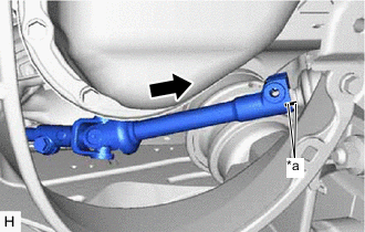
*a Matchmark Align the matchmarks on the steering sliding with shaft yoke sub-assembly with the matchmarks on the power steering link assembly.
-
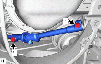
Install the bolt (B) and tighten the bolt (A).
35.3 N*m 360 kgf*cm 26 ft.*lbf
-
- Click here
INSTALL FRONT LOWER SUSPENSION MEMBER PROTECTOR
- Click here
INSTALL NO. 2 FRAME CROSSMEMBER ASSEMBLY
- Click here
INSTALL NO. 1 FRAME CROSSMEMBER ASSEMBLY
- Click here
INSTALL NO. 1 OIL COOLER BRACKET
- Click here
INSTALL OIL COOLER BRACKET
- Click here
INSTALL FRONT FENDER LINER LH
- Click here
INSTALL FRONT FENDER LINER RH
- Click here
INSTALL FRONT SUSPENSION MEMBER BRACE SUB-ASSEMBLY
- Click here
INSTALL REAR ENGINE UNDER COVER LH
- Click here
INSTALL REAR ENGINE UNDER COVER RH
Tip:Perform the same procedure as for the LH side.
- Click here
INSTALL NO. 1 ENGINE UNDER COVER ASSEMBLY
- Click here
INSTALL FRONT WHEELS
- Click here
ALIGN FRONT WHEELS FACING STRAIGHT AHEAD
- Click here
CONNECT CABLE TO NEGATIVE BATTERY TERMINAL
Note:When disconnecting the cable, some systems need to be initialized after the cable is reconnected.
- Click here
INSPECT AND ADJUST FRONT WHEEL ALIGNMENT
- Click here
ROTATION ANGLE SENSOR INITIALIZATION AND TORQUE SENSOR ZERO POINT CALIBRATION