STEERING KNUCKLE INSTALLATION

CAUTION / NOTICE / HINT
Tech Tips
-
Use the same procedure for the RH side and LH side.
-
The following procedure is for the LH side.
PROCEDURE
-
INSTALL STEERING KNUCKLE
-
Install the steering knuckle to the front upper suspension arm assembly with the nut.
- Torque:
- 87 N*m { 887 kgf*cm, 64 ft.*lbf }
Note
Prevent oil from adhering to the threaded and tapered parts.
-
Install a new clip.
Note
Further tighten the nut up to 60° if the holes for the clip are not aligned.
-
-
INSTALL FRONT LOWER BALL JOINT ASSEMBLY
-
Install the front lower ball joint assembly to the steering knuckle with the 2 bolts.
- Torque:
- 120 N*m { 1224 kgf*cm, 89 ft.*lbf }
-
-
CONNECT TIE ROD ASSEMBLY
-
INSTALL FRONT DISC BRAKE DUST COVER
-
Install the front disc brake dust cover to the steering knuckle with the 4 bolts.
- Torque:
- 8.0 N*m { 82 kgf*cm, 71 in.*lbf }
-
-
INSTALL FRONT AXLE HUB SUB-ASSEMBLY
-
INSPECT FRONT AXLE HUB BEARING LOOSENESS
-
INSPECT FRONT AXLE HUB RUNOUT
-
INSTALL FRONT DISC
-
INSTALL FRONT DISC BRAKE CALIPER ASSEMBLY
-
Install the front disc brake caliper assembly to the steering knuckle with the 2 bolts.
- Torque:
- 135 N*m { 1377 kgf*cm, 100 ft.*lbf }
Note
Do not twist the front flexible hose when installing the front disc brake caliper assembly.
-
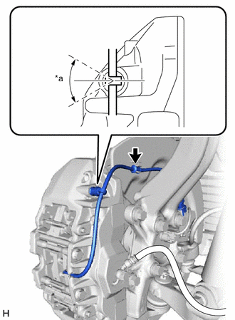
*a 0° +/- 30° Check that the bleeder plug cap of the pad wear indicator wire assembly is installed to the front disc brake caliper assembly as shown in the illustration.
Note
Perform this check without the pad wear indicator wire assembly installed to the front disc brake dust cover clamp.
-
Install the pad wear indicator wire assembly to the clamp of front disc brake dust cover.
-
-
INSTALL FRONT SKID CONTROL SENSOR WIRE
-
Install the front skid control sensor wire to the steering knuckle with the bolt.
- Torque:
- 8.5 N*m { 87 kgf*cm, 75 in.*lbf }
Note
Do not twist the front skid control sensor wire when installing it.
-
Connect the front skid control sensor wire connector to the front axle hub sub-assembly.
Note
Do not twist the front skid control sensor wire when installing it.
-
Connect the pad wear indicator wire connector to the front skid control sensor wire clamp.
Note
Do not twist the pad wear indicator wire when installing it.
-
-
INSTALL FRONT WHEEL
-
INSPECT AND ADJUST FRONT WHEEL ALIGNMENT
-
CHECK FOR SPEED SENSOR SIGNAL