ENGINE ASSEMBLY INSTALLATION
CAUTION / NOTICE / HINT
Note
When the oil cooler assembly (for air cooled type) has been removed/installed or the oil cooler hose sub-assembly has been disconnected/reconnected, check the engine oil level after warming up the engine oil to between 100°C and 120°C to open the thermostat between the engine and oil cooler assembly (for air cooled type).
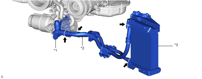
| *1 | thermostat (thermostat housing assembly) | *2 | oil cooler hose sub-assembly |
| *3 | oil cooler assembly (for air cooled type) | - | - |
Tech Tips
Enter the following menus: Powertrain / Engine / Data List / Engine Oil Temperature.
Powertrain > Engine > Data List
| Tester Display |
|---|
| Engine Oil Temperature |
CAUTION / NOTICE / HINT
CAUTION:
The engine assembly with transmission is very heavy. Be sure to follow the procedure described in the repair manual, or the engine lifter may suddenly drop.
PROCEDURE
-
INSTALL ENGINE HANGER
-
REMOVE ENGINE FROM ENGINE STAND
-
Remove the engine assembly from the engine stand.
-
-
INSTALL FRONT ENGINE MOUNTING INSULATOR
Tech Tips
Perform this procedure only when replacement of the front engine mounting insulator is necessary.
-
Install the 2 front engine mounting insulators to the front suspension crossmember sub-assembly with the 2 nuts.
- Torque:
- 70 N*m { 714 kgf*cm, 52 ft.*lbf }
-
Install the 2 engine mounting spacers.
-
-
INSTALL FRONT SUSPENSION CROSSMEMBER SUB-ASSEMBLY
-
Install the front suspension crossmember sub-assembly to the engine assembly with the 2 nuts.
- Torque:
- 35 N*m { 357 kgf*cm, 26 ft.*lbf }
-
-
INSTALL DRIVE PLATE AND RING GEAR SUB-ASSEMBLY
-
INSTALL REAR ENGINE MOUNTING HEAT INSULATOR
-
Install the rear engine mounting heat insulator to the rear engine mounting insulator with the 4 bolts.
- Torque:
- 13 N*m { 133 kgf*cm, 10 ft.*lbf }
-
-
INSTALL REAR ENGINE MOUNTING INSULATOR
Tech Tips
Perform this procedure only when replacement of the rear engine mounting insulator is necessary.
-
Install the rear engine mounting insulator to the automatic transmission assembly with the 4 bolts.
- Torque:
- 40 N*m { 408 kgf*cm, 30 ft.*lbf }
Tech Tips
Make sure that the claw is facing towards the front of the vehicle.
-
-
INSTALL REAR ENGINE MOUNTING MEMBER
Tech Tips
Perform this procedure only when replacement of the rear engine mounting insulator is necessary.
-
Install the rear engine mounting member to the rear engine mounting insulator with the 4 nuts.
- Torque:
- 13 N*m { 133 kgf*cm, 10 ft.*lbf }
-
-
INSTALL AUTOMATIC TRANSMISSION ASSEMBLY
-
INSTALL DRIVE PLATE AND TORQUE CONVERTER ASSEMBLY SETTING BOLT
-
INSTALL STARTER ASSEMBLY
-
INSTALL GENERATOR ASSEMBLY
-
INSTALL COMPRESSOR ASSEMBLY WITH PULLEY
-
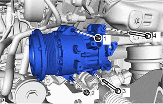
Install the compressor assembly with pulley with the 2 bolts and 2 nuts.
- Torque:
- 24.5 N*m { 250 kgf*cm, 18 ft.*lbf }
Tech Tips
Tighten the bolts and nuts in the order shown in the illustration.
-
-
INSTALL OIL COOLER TUBE
-
Install the oil cooler tube with the 3 bolts.
- Torque:
- 13.5 N*m { 138 kgf*cm, 10 ft.*lbf }
-
Engage the clamp to the oil cooler tube.
-
-
CONNECT WIRE HARNESS
-
INSTALL V-RIBBED BELT
-
INSTALL NO. 3 EXHAUST MANIFOLD HEAT INSULATOR
-
INSTALL EXHAUST MANIFOLD SUB-ASSEMBLY LH
-
INSTALL NO. 2 EXHAUST MANIFOLD HEAT INSULATOR
-
INSTALL EXHAUST MANIFOLD SUB-ASSEMBLY RH
-
INSTALL NO. 1 EXHAUST MANIFOLD HEAT INSULATOR
-
INSTALL DIFFERENTIAL PRESSURE SENSOR (w/ Differential Pressure Sensor)
-
for Bank 1:
-
for Bank 2:
-
-
CONNECT NO. 2 VACUUM PIPE (w/ Differential Pressure Sensor)
-
Temporarily install the No. 2 vacuum pipe to the exhaust manifold sub-assembly LH.
-
Connect the No. 2 vacuum pipe to the exhaust manifold sub-assembly LH with the bolt.
- Torque:
- 10 N*m { 102 kgf*cm, 7 ft.*lbf }
-
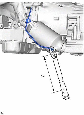
*a Torque Wrench Fulcrum Length Using a 14 mm union nut wrench, connect the No. 2 vacuum pipe to the exhaust manifold sub-assembly LH with the bolt.
- Torque:
- Specified tightening torque
- 30 N*m { 306 kgf*cm, 22 ft.*lbf }
Tech Tips
-
Calculate the torque wrench reading when changing the fulcrum length of the torque wrench.
-
When using a 14 mm union nut wrench (fulcrum length of 25 mm (0.984 in.)) + torque wrench (fulcrum length of 180 mm (7.09 in.)):
26.3 N*m (268 kgf*cm, 19 ft.*lbf)
-
Connect the No. 2 pipe with the nut.
- Torque:
- 10 N*m { 102 kgf*cm, 7 ft.*lbf }
-
-
CONNECT NO. 1 VACUUM PIPE (w/ Differential Pressure Sensor)
-
Temporarily install the No. 1 vacuum pipe to the exhaust manifold sub-assembly RH.
-
Connect the No. 1 vacuum pipe to the exhaust manifold sub-assembly RH with the bolt.
- Torque:
- 10 N*m { 102 kgf*cm, 7 ft.*lbf }
-
Connect the No. 1 pipe with the nut.
- Torque:
- 10 N*m { 102 kgf*cm, 7 ft.*lbf }
-
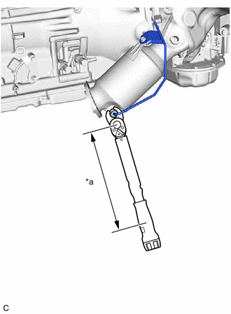
*a Torque Wrench Fulcrum Length Using a 14 mm union nut wrench, connect the No. 1 vacuum pipe to the exhaust manifold sub-assembly RH with the bolt.
- Torque:
- Specified tightening torque
- 30 N*m { 306 kgf*cm, 22 ft.*lbf }
Tech Tips
-
Calculate the torque wrench reading when changing the fulcrum length of the torque wrench.
-
When using a 14 mm union nut wrench (fulcrum length of 25 mm (0.984 in.)) + torque wrench (fulcrum length of 180 mm (7.09 in.)):
26.3 N*m (268 kgf*cm, 19 ft.*lbf)
-
-
INSTALL NO. 1 VACUUM TRANSMITTING HOSE ASSEMBLY (w/ Differential Pressure Sensor)
-
INSTALL NO. 2 VACUUM TRANSMITTING HOSE ASSEMBLY (w/ Differential Pressure Sensor)
-
INSTALL ENGINE MOUNTING DAMPER
-
Install the 2 engine mounting dampers with the 2 bolts.
- Torque:
- 10 N*m { 102 kgf*cm, 7 ft.*lbf }
-
-
INSTALL ENGINE UNDER COVER SUB-ASSEMBLY RH
-
Engage the 2 clamps to install the engine under cover sub-assembly RH to the front suspension crossmember sub-assembly.
-
-
INSTALL ENGINE UNDER COVER SUB-ASSEMBLY LH
-
Engage the 2 clamps to install the engine under cover sub-assembly LH to the front suspension crossmember sub-assembly.
-
-
INSTALL ENGINE OIL LEVEL DIPSTICK GUIDE
-
INSTALL ENGINE OIL LEVEL DIPSTICK
-
INSTALL ENGINE ASSEMBLY WITH TRANSMISSION
-
Set the engine assembly with transmission on an engine lifter.
Note
-
Using height adjustment attachments and plate lift attachments, place the engine assembly with transmission horizontally.
-
Do not perform any procedure while the engine assembly is suspended because doing so may cause the engine assembly to drop, resulting in injury. However, the engine assembly needs to be suspended when it is installed to or removed from an engine stand.
-
To prevent the oil pan from deforming, do not place any attachments under the oil pan of the engine assembly with transmission.
-
-
Remove the 2 bolts and 2 No. 1 engine hangers.
-
Install the engine assembly with transmission to the vehicle.
Note
Make sure that the engine assembly with transmission is clear of all wiring, hoses and the steering sliding yoke sub-assembly.
-
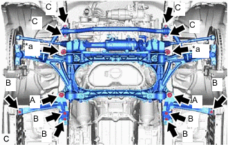
*a Nut Install the strut bar bracket reinforcement LH, strut bar bracket reinforcement RH and front suspension crossmember sub-assembly with the 8 bolts and 2 nuts.
- Torque:
- Bolt (A)
- 194 N*m { 1978 kgf*cm, 143 ft.*lbf }
- Bolt (B)
- 57 N*m { 581 kgf*cm, 42 ft.*lbf }
- Nut
- 151 N*m { 1540 kgf*cm, 111 ft.*lbf }
-
Connect the front No. 2 stabilizer bracket LH and front No. 2 stabilizer bracket RH with the 4 bolts.
- Torque:
- Bolt (C)
- 49 N*m { 500 kgf*cm, 36 ft.*lbf }
-
Install the rear engine mounting member to the vehicle body with the 4 bolts.
- Torque:
- 34.7 N*m { 354 kgf*cm, 26 ft.*lbf }
-
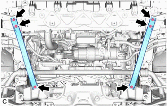
Install the 2 No. 2 frame crossmember assemblies with the 6 bolts.
- Torque:
- 20 N*m { 204 kgf*cm, 15 ft.*lbf }
-
Install the 2 oil cooler brackets with the 8 nuts and 2 bolts.
- Torque:
- 8.0 N*m { 82 kgf*cm, 71 in.*lbf }
-
-
CONNECT WIRE HARNESS (for LHD)
-
Engage the 2 wire harness clamps to the power steering link assembly.
-
Connect the 3 power steering link assembly connectors.
Tech Tips
For the connector with lock lever, fully insert the connector and push down the lock lever to engage the lock.
-
-
CONNECT WIRE HARNESS (for RHD)
-
Engage the 2 wire harness clamps to the power steering link assembly.
-
Connect the 3 power steering link assembly connectors.
Tech Tips
For the connector with lock lever, fully insert the connector and push down the lock lever to engage the lock.
-
-
CONNECT FLOOR SHIFT GEAR SHIFTING ROD SUB-ASSEMBLY
-
INSTALL TIE ROD ASSEMBLY LH
-
INSTALL TIE ROD ASSEMBLY RH
Tech Tips
Perform the same procedure as for the LH side.
-
INSTALL STEERING SLIDING YOKE SUB-ASSEMBLY
-
INSTALL FRONT LOWER BALL JOINT ASSEMBLY LH
-
INSTALL FRONT LOWER BALL JOINT ASSEMBLY RH
Tech Tips
Perform the same procedure as for the LH side.
-
CONNECT FRONT SHOCK ABSORBER ASSEMBLY LH
-
Connect the front shock absorber assembly LH to the front suspension lower arm assembly LH with the bolt and nut.
- Torque:
- 108 N*m { 1101 kgf*cm, 80 ft.*lbf }
Note
-
Insert the bolt from the rear of the vehicle.
-
Because the nut has its own stopper, do not turn the nut. Tighten the bolt with the nut secured.
-
-
CONNECT FRONT SHOCK ABSORBER ASSEMBLY RH
Tech Tips
Perform the same procedure as for the LH side.
-
INSTALL FRONT SKID CONTROL SENSOR WIRE
-
INSTALL PROPELLER WITH CENTER BEARING SHAFT ASSEMBLY
-
INSTALL NO. 1 ENGINE ROOM RELAY BLOCK AND NO. 1 JUNCTION BLOCK ASSEMBLY
for LHD: Click here
for RHD: Click here
-
INSTALL BATTERY TRAY
for LHD: Click here
for RHD: Click here
-
INSTALL POWER STEERING ECU ASSEMBLY
-
for LHD
-
for RHD
-
-
CONNECT WIRE HARNESS (for LHD)
-
Connect the ground cable to the generator assembly with the bolt.
- Torque:
- 21 N*m { 214 kgf*cm, 15 ft.*lbf }
-
Engage the clamp.
-
Engine room LH side:
-
Connect the engine wire to the engine room ECU box.
-
Connect the engine wire clamp.
-
-
Engine room RH side:
-
Install the No. 3 engine wire to the vehicle body with the bolt.
- Torque:
- 8.5 N*m { 87 kgf*cm, 75 in.*lbf }
-
Engage the 2 claws to connect the No. 4 engine wire to the No. 1 engine room relay block and No. 1 junction block assembly.
-
Engage the No. 4 engine wire clamp.
-
Install the nut to the No. 1 engine room relay block and No. 1 junction block assembly.
- Torque:
- 10.5 N*m { 107 kgf*cm, 8 ft.*lbf }
-
Install the No. 1 engine room relay block cover to the No. 1 engine room relay block and No. 1 junction block assembly.
-
Connect the No. 2 engine wire to the positive (+) battery terminal with the nut.
- Torque:
- 7.6 N*m { 77 kgf*cm, 67 in.*lbf }
-
Engage the No. 2 engine wire clamp.
-
Engage the 4 clamps to install the No. 1 center cowl top ventilator louver to the cowl top ventilator louver sub-assembly.
-
-
-
CONNECT WIRE HARNESS (for RHD)
-
Connect the ground cable to the generator assembly with the bolt.
- Torque:
- 21 N*m { 214 kgf*cm, 15 ft.*lbf }
-
Engage the clamp.
-
Engine room LH side:
-
Connect the engine wire to the engine room ECU box.
-
Engage the engine wire clamp.
-
Engage the 2 claws to connect the No. 4 engine wire to the No. 1 engine room relay block and No. 1 junction block assembly.
-
Engage the No. 4 engine wire clamp.
-
Install the nut to the No. 1 engine room relay block and No. 1 junction block assembly.
- Torque:
- 10.5 N*m { 107 kgf*cm, 8 ft.*lbf }
-
Install the No. 1 engine room relay block cover to the No. 1 engine room relay block and No. 1 junction block assembly.
-
Connect the No. 2 engine wire to the positive (+) battery terminal with the nut.
- Torque:
- 7.6 N*m { 77 kgf*cm, 67 in.*lbf }
-
Engage the No. 2 engine wire clamp.
-
Engage the 4 clamps to install the No. 1 center cowl top ventilator louver to the cowl top ventilator louver sub-assembly.
-
-
Engine room RH side:
-
Connect the No. 3 engine wire to the vehicle body with the bolt.
- Torque:
- 8.5 N*m { 87 kgf*cm, 75 in.*lbf }
-
-
-
INSTALL ENGINE ROOM ECU COVER
-
CONNECT SUCTION HOSE
-
CONNECT NO. 1 COOLER REFRIGERANT DISCHARGE HOSE
-
CONNECT FUEL TUBE SUB-ASSEMBLY
-
Connect the fuel tube sub-assembly to the fuel pipe.
CAUTION:
Align the fuel tube connector with the fuel pipe, then push the fuel tube connector in until the retainer makes a "click" sound. If it is difficult to push the fuel tube connector in, apply a small amount of clean engine oil to the tip of the fuel pipe. After connecting, pull the fuel pipe and fuel tube connector to make sure that they are securely connected.
-
Install the fuel pipe clamp.
-
-
CONNECT NO. 2 FUEL TUBE SUB-ASSEMBLY
-
Connect the No. 2 fuel tube sub-assembly to the fuel pipe.
CAUTION:
Align the fuel tube connector with the fuel pipe, then push the fuel tube connector in until the retainer makes a "click" sound. If it is difficult to push the fuel tube connector in, apply a small amount of clean engine oil to the tip of the fuel pipe. After connecting, pull the fuel pipe and fuel tube connector to make sure that they are securely connected.
-
Install the fuel pipe clamp.
-
-
CONNECT NO. 1 FUEL VAPOR FEED HOSE
-
Connect the No. 1 fuel vapor feed hose to the purge valve (purge VSV) and slide the clip to secure it.
-
-
CONNECT UNION TO CHECK VALVE HOSE (for LHD)
-
Connect the union to check valve hose to the intake air surge tank assembly and slide the clip to secure it.
-
Engage the union to check valve hose to the clamp.
-
-
CONNECT UNION TO CHECK VALVE HOSE (for RHD)
-
Connect the union to check valve hose to the intake air surge tank assembly and slide the clip to secure it.
-
Engage the union to check valve hose to the clamp.
-
-
CONNECT HEATER WATER OUTLET HOSE
-
Connect the heater water outlet hose to the No. 3 water by-pass pipe and slide the clip to secure it.
-
Install the water hose set.
-
-
CONNECT HEATER WATER INLET HOSE
-
Connect the heater water inlet hose to the No. 3 water by-pass pipe and slide the clip to secure it.
-
Install the water hose set.
-
-
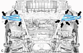
INSTALL FRONT SUSPENSION UPPER TO COWL BRACE RH
-
Install the front suspension upper to cowl brace RH with the bolt and 3 nuts.
- Torque:
- 19 N*m { 194 kgf*cm, 14 ft.*lbf }
-
-
INSTALL FRONT SUSPENSION UPPER TO COWL BRACE LH
-
Install the front suspension upper to cowl brace LH with the bolt and 3 nuts.
- Torque:
- 19 N*m { 194 kgf*cm, 14 ft.*lbf }
-
-
INSTALL OIL COOLER HOSE SUB-ASSEMBLY
-
Apply a small amount of engine oil to 2 new O-rings and install them to the oil cooler hose sub-assembly.
Note
Do not damage the O-rings.
-
Connect the oil cooler hose sub-assembly with the 2 bolts.
- Torque:
- 10 N*m { 102 kgf*cm, 7 ft.*lbf }
-
-
CONNECT NO. 2 OIL COOLER OUTLET HOSE
-
Connect the No. 2 oil cooler outlet hose to the oil cooler assembly and slide the clip to secure it.
-
-
CONNECT NO. 2 OIL COOLER INLET HOSE
-
Connect the No. 2 oil cooler inlet hose to the oil cooler assembly and slide the clip to secure it.
-
-
CONNECT NO. 2 RADIATOR HOSE
-
Connect the No. 2 radiator hose to the water inlet and slide the clip to secure it.
-
-
CONNECT NO. 1 RADIATOR HOSE
-
Connect the No. 1 radiator hose to the front water by-pass joint and slide the clip to secure it.
-
-
INSTALL RADIATOR RESERVE TANK ASSEMBLY
-
INSTALL AIR CLEANER CASE SUB-ASSEMBLY
Tech Tips
Perform this procedure only when replacement of the air cleaner case sub-assembly is necessary.
-
Install the air cleaner case sub-assembly with the 2 bolts.
- Torque:
- 5.0 N*m { 51 kgf*cm, 44 in.*lbf }
-
Connect the vacuum switching valve connector and engage the clamp.
-
Connect the vacuum hose assembly and engage the 2 clamps.
-
-
INSTALL AIR CLEANER FILTER ELEMENT SUB-ASSEMBLY
-
Install the air cleaner filter element sub-assembly to the air cleaner case sub-assembly.
-
-
INSTALL AIR CLEANER CAP WITH AIR CLEANER HOSE
-
INSTALL INLET NO. 1 AIR CLEANER
-
INSTALL NO. 1 EXHAUST PIPE SUPPORT BRACKET SUB-ASSEMBLY
-
INSTALL NO. 2 ENGINE UNDER COVER
-
Install the No. 2 engine under cover with the 2 screws.
-
-
INSTALL FRONT LOWER SUSPENSION MEMBER PROTECTOR
-
Install the front lower suspension member protector with the 4 bolts.
- Torque:
- 5.5 N*m { 56 kgf*cm, 49 in.*lbf }
-
-
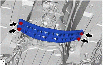
INSTALL FRONT SUSPENSION MEMBER BRACE SUB-ASSEMBLY
-
Install the front suspension member brace sub-assembly with the 6 bolts and 4 nuts.
- Torque:
- Bolt
- 52 N*m { 530 kgf*cm, 38 ft.*lbf }
- Nut
- 19 N*m { 194 kgf*cm, 14 ft.*lbf }
-
-
INSTALL FRONT FENDER LINER LH
-
Install the front fender liner LH with the 2 screws.
-
-
INSTALL FRONT FENDER LINER RH
-
Install the front fender liner RH with the 2 screws.
-
-
INSTALL REAR ENGINE UNDER COVER LH
-
Install the rear engine under cover LH with the screw.
-
-
INSTALL REAR ENGINE UNDER COVER RH
Tech Tips
Perform the same procedure as for the LH side.
-
CONNECT CABLE TO NEGATIVE BATTERY TERMINAL
-
Connect the cable to the negative (-) battery terminal with the nut.
- Torque:
- 5.5 N*m { 56 kgf*cm, 49 in.*lbf }
Note
When disconnecting the cable, some systems need to be initialized after the cable is reconnected.
-
-
ADD ENGINE OIL
-
ADD ENGINE COOLANT
-
ADD AUTOMATIC TRANSMISSION FLUID
-
INSPECT FOR REFRIGERANT
-
for HFC-134a (R134a)
-
for HFO-1234yf (R1234yf)
-
-
INSPECT SHIFT LEVER POSITION
-
ADJUST SHIFT LEVER POSITION
-
INSPECT FOR COOLANT LEAK
-
INSPECT FOR ENGINE OIL LEAK
-
INSPECT FOR FUEL LEAK
-
INSPECT FOR EXHAUST GAS LEAK
-
INSPECT FOR REFRIGERANT LEAK
-
for HFC-134a (R134a)
-
for HFO-1234yf (R1234yf)
-
-
INSTALL FRONT WHEELS
-
ALIGN FRONT WHEELS FACING STRAIGHT AHEAD
-
INSPECT AND ADJUST FRONT WHEEL ALIGNMENT
-
PERFORM INITIALIZATION
-
INSPECT IGNITION TIMING
-
INSPECT ENGINE IDLE SPEED
-
INSPECT CO/HC
-
INSPECT ENGINE COOLANT LEVEL IN RESERVOIR
-
CHECK ENGINE OIL LEVEL
-
INSTALL NO. 1 ENGINE UNDER COVER ASSEMBLY
-
Install the No. 1 engine under cover assembly with the 13 screws and 3 clips.
-
-
INSTALL COOL AIR INTAKE DUCT SEAL
-
INSTALL V-BANK COVER SUB-ASSEMBLY
-
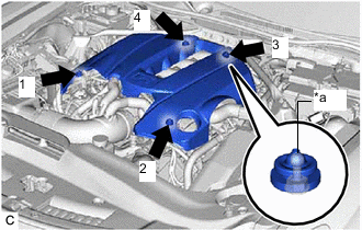
*a Tip (Sphere) Attach the 4 clips in the order shown in the illustration to install the V-bank cover sub-assembly.
Note
-
Securely attach the clips.
-
If the clips are forcibly attached or struck with an object, they may be damaged.
-
Do not apply any oil to the tips (sphere).
-
-