AIR CONDITIONING UNIT INSTALLATION
PROCEDURE
-
TEMPORARILY INSTALL AIR CONDITIONER UNIT ASSEMBLY
-
Temporarily install the air conditioner unit assembly to the instrument panel reinforcement assembly with the 3 bolts.
-
-
INSTALL INSTRUMENT PANEL REINFORCEMENT ASSEMBLY WITH AIR CONDITIONER UNIT ASSEMBLY
Note
-
Be sure to support the air conditioner unit assembly when installing it. Failure to do so may cause the bracket of the air conditioner unit assembly to break.
-
When installing the air conditioner unit assembly, eliminate static electricity by touching the vehicle body to prevent the components from being damaged.
-
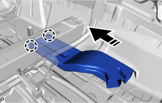
Temporarily install the instrument panel reinforcement assembly with air conditioner unit assembly as shown in the illustration.
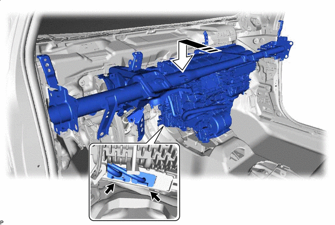

Install in this Direction - - -
Connect each connector.
-
Install the 4 bolts (A).
- Torque:
- 25 N*m { 255 kgf*cm, 18 ft.*lbf }
-
Connect the parking brake pedal assembly with the bolt (B).
- Torque:
- 15 N*m { 153 kgf*cm, 11 ft.*lbf }
-
Temporarily install the nut.
-
Install the 2 bolts.
- Torque:
- 25 N*m { 255 kgf*cm, 18 ft.*lbf }
-
Connect the drain cooler hose.
-
for LHD:
-
Engage each clamp.
-
Connect the relay block assembly with the bolt.
- Torque:
- 8.0 N*m { 82 kgf*cm, 71 in.*lbf }
-
Connect the 3 earth wires with the 3 bolts.
- Torque:
- 8.5 N*m { 87 kgf*cm, 75 in.*lbf }
-
Connect each connector.
-
-
for RHD:
-
Engage each clamp.
-
Connect the relay block assembly with the bolt.
- Torque:
- 8.0 N*m { 82 kgf*cm, 71 in.*lbf }
-
Connect the 3 earth wires with the 3 bolts.
- Torque:
- 8.5 N*m { 87 kgf*cm, 75 in.*lbf }
-
Connect each connector.
-
-
-
INSTALL LOWER DEFROSTER NOZZLE ASSEMBLY
-
Engage the 6 claws to install the lower defroster nozzle assembly.
-
-
INSTALL INSTRUMENT PANEL JUNCTION BLOCK ASSEMBLY WITH MAIN BODY ECU
-
INSTALL NO. 3 INSTRUMENT PANEL TO COWL BRACE SUB-ASSEMBLY
-
Install the No. 3 instrument panel to cowl brace sub-assembly with the bolt and nut.
- Torque:
- Bolt
- 10 N*m { 102 kgf*cm, 7 ft.*lbf }
- Nut
- 6.0 N*m { 61 kgf*cm, 53 in.*lbf }
-
for LHD:
-
Engage the clamp and 2 claws to connect the DLC3 connector.
-
-
-
INSTALL NO. 2 INSTRUMENT PANEL BRACE SUB-ASSEMBLY
-
Install the No. 2 instrument panel brace sub-assembly with the bolt and nut.
- Torque:
- Bolt
- 20 N*m { 204 kgf*cm, 15 ft.*lbf }
- Nut
- 18 N*m { 184 kgf*cm, 13 ft.*lbf }
-
Temporarily install the screw.
Tech Tips
Do not fully tighten the screw.
-
Engage each clamp.
-
Install the front floor mat to its original position as shown in the illustration.
-
-
INSTALL NO. 1 INSTRUMENT PANEL BRACE SUB-ASSEMBLY
-
Install the No. 1 instrument panel brace sub-assembly with the bolt and nut.
- Torque:
- Bolt
- 20 N*m { 204 kgf*cm, 15 ft.*lbf }
- Nut
- 18 N*m { 184 kgf*cm, 13 ft.*lbf }
-
Temporarily install the screw.
Tech Tips
Do not fully tighten the screw.
-
w/ PTC Heater:
-
Connect the earth wire with the bolt.
- Torque:
- 8.5 N*m { 87 kgf*cm, 75 in.*lbf }
-
-
Connect the earth wire with the bolt.
- Torque:
- 8.5 N*m { 87 kgf*cm, 75 in.*lbf }
-
Engage each clamp.
-
Install the front floor mat to its original position as shown in the illustration.
-
-
INSTALL AIR CONDITIONER UNIT ASSEMBLY
-
for LHD:
-
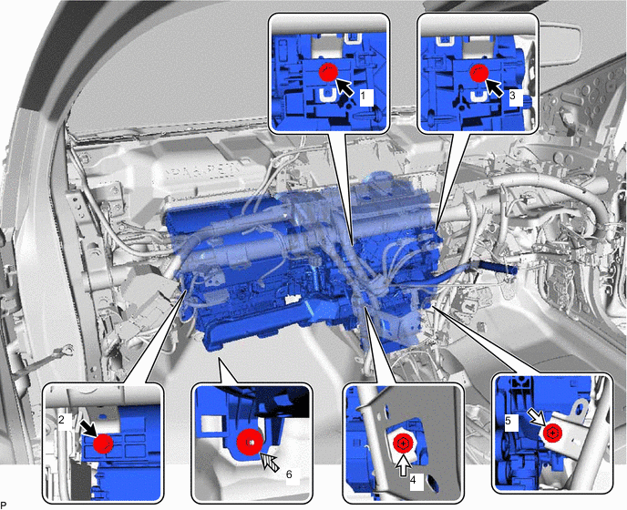
Tighten the 3 bolts, 2 screws and nut to install the air conditioner unit assembly.
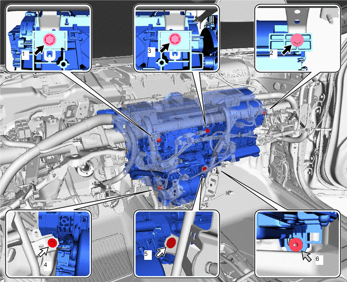

Bolt 
Screw 
Nut - - - Torque:
- Bolt
- 9.8 N*m { 100 kgf*cm, 87 in.*lbf }
- Nut
- 9.8 N*m { 100 kgf*cm, 87 in.*lbf }
Note
Tighten the bolts, screws and nut in the order shown in the illustration.
-
-
for RHD:
-
Tighten the 3 bolts, 2 screws and nut to install the air conditioner unit assembly.
Bolt Screw Nut - - - Torque:
- Bolt
- 9.8 N*m { 100 kgf*cm, 87 in.*lbf }
- Nut
- 9.8 N*m { 100 kgf*cm, 87 in.*lbf }
Note
Tighten the bolts, screws and nut in the order shown in the illustration.
-
-
-
INSTALL NO. 3 DASH PANEL INSULATOR PAD
-
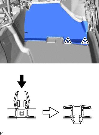
Install the No. 3 dash panel insulator pad with 2 new clips as shown in the illustration.
-
-
INSTALL REAR NO. 1 AIR DUCT
-
Engage the 4 claws to install the rear No. 1 air duct.
-
-
INSTALL REAR NO. 4 AIR DUCT
-
Engage the 2 claws to install the rear No. 4 air duct.
-
-
INSTALL REAR NO. 5 AIR DUCT
-
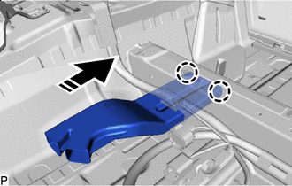
Install in this Direction Engage the 2 claws to install the rear No. 5 air duct as shown in the illustration.
-
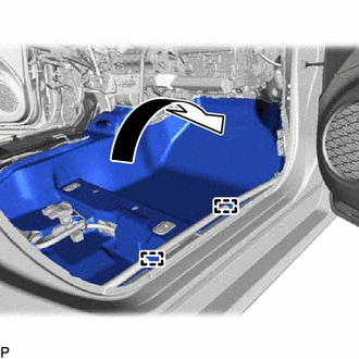
Install the front floor carpet assembly to its original position as shown in the illustration.
-
Engage the 2 guides.
-
Install the 2 front floor carpet clips.
-
-
INSTALL REAR NO. 2 AIR DUCT
-
Engage the 2 claws to install the rear No. 2 air duct.
-
-
INSTALL REAR NO. 3 AIR DUCT
-
Install in this Direction Engage the 2 claws to install the rear No. 3 air duct as shown in the illustration.
-
Install the front floor carpet assembly to its original position as shown in the illustration.
-
Engage the 2 guides.
-
Install the 2 front floor carpet clips.
-
-
INSTALL FRONT FLOOR CAUTION PLATE COVER
-
Install in this Direction Engage the guide and claw to install the front floor caution plate cover as shown in the illustration.
-
-
INSTALL FRONT NO. 2 CONSOLE BOX INSERT
-
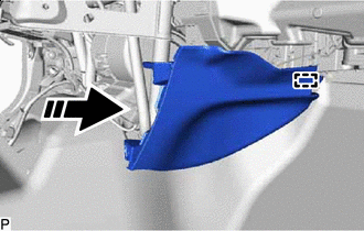
Install in this Direction Engage the guide as shown in the illustration.
-
Install in this Direction Engage the claw and clip to install the front No. 2 console box insert as shown in the illustration.
-
-
INSTALL FRONT NO. 1 CONSOLE BOX INSERT
-
Install in this Direction Engage the guide as shown in the illustration.
-
Install in this Direction Engage the claw and clip to install the front No. 1 console box insert as shown in the illustration.
-
-
INSTALL COOLER (ROOM TEMP. SENSOR) THERMISTOR
-
Connect the aspirator and connector to install the cooler (room temp. sensor) thermistor.
-
-
INSTALL SHIFT LOCK CONTROL UNIT ASSEMBLY
-
INSTALL TELEMATICS TRANSCEIVER WITH ANTENNA CORD (w/ Telematics Transceiver)
-
INSTALL ECU INTEGRATION BOX LH (for RHD)
-
INSTALL ECU INTEGRATION BOX RH (for LHD)
-
INSTALL DOUBLE LOCK DOOR CONTROL RELAY ASSEMBLY (w/ Double Locking System)
-
INSTALL CLEARANCE WARNING ECU ASSEMBLY (w/ TOYOTA Parking Assist-sensor System)
-
INSTALL NO. 2 CLEARANCE WARNING BUZZER (w/ TOYOTA Parking Assist-sensor System)
-
INSTALL NO. 1 CLEARANCE WARNING BUZZER (w/ TOYOTA Parking Assist-sensor System)
-
INSTALL WINDSHIELD WIPER RELAY ASSEMBLY (w/ Rain Sensor)
-
INSTALL DRIVING SUPPORT ECU ASSEMBLY (w/ Toyota Safety Sense P)
-
INSTALL SKID CONTROL BUZZER (w/ Toyota Safety Sense P)
-
INSTALL STEERING COLUMN ASSEMBLY
-
INSTALL LOWER INSTRUMENT PANEL SUB-ASSEMBLY
-
INSTALL FRONT SEAT ASSEMBLY LH
for Manual seat:
for Power seat:
-
INSTALL FRONT SEAT ASSEMBLY RH
-
CONNECT AIR CONDITIONER TUBE AND ACCESSORY ASSEMBLY
-
Remove the vinyl tape from the air conditioner tube and accessory assembly.
-
Sufficiently apply compressor oil to a new O-ring and the fitting surface of the air conditioner tube and accessory assembly.
Compressor Oil ND-OIL 11 or equivalent -
Install the O-ring to the air conditioner tube and accessory assembly.
Note
Keep the O-ring and O-ring fitting surface free of foreign matter.
-
Connect the air conditioner tube and accessory assembly.
-
-
CONNECT SUCTION PIPE SUB-ASSEMBLY
-
Remove the vinyl tape from the suction pipe sub-assembly.
-
Sufficiently apply compressor oil to a new O-ring and the fitting surface of the suction pipe sub-assembly.
Compressor Oil ND-OIL 11 or equivalent -
Install the O-ring to the suction pipe sub-assembly.
Note
Keep the O-ring and O-ring fitting surface free of foreign matter.
-
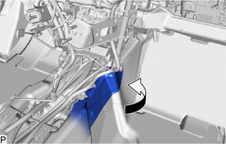
Connect the suction pipe sub-assembly.
-
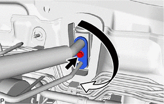
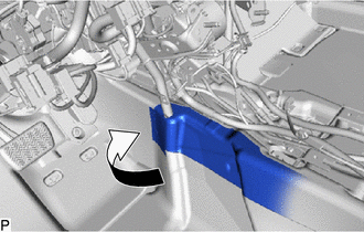
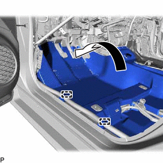
Rotate the hook connector as shown in the illustration.
-
Insert the hose joint into the fitting hole securely and install the bolt.
- Torque:
- 9.8 N*m { 100 kgf*cm, 87 in.*lbf }
-
-
CONNECT INLET HEATER WATER HOSE A
-
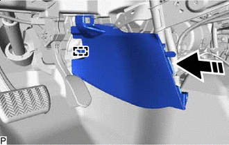
w/o Exhaust Heat Recirculation System:
-
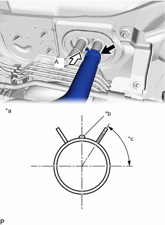
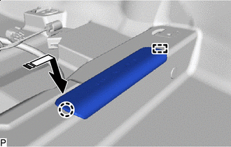
*a View A *b Marking (Brown) *c Clip Installation Angle (60°) Connect the inlet heater water hose A with the marking facing up and engage the clip within the area shown in the illustration.
Note
Do not apply excessive force to the inlet heater water hose A.
-
-
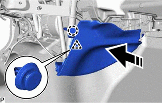
w/ Exhaust Heat Recirculation System:
-

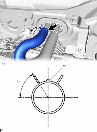
*a View A *b Marking (Blue) *c Clip Installation Angle (60°) Connect the inlet heater water hose A with the marking facing up and engage the clip within the area shown in the illustration.
Note
Do not apply excessive force to the inlet heater water hose A.
-
-
-
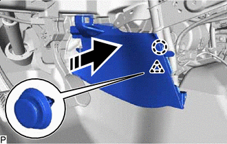
CONNECT OUTLET HEATER WATER HOSE A (w/o Exhaust Heat Recirculation System)
-
*a View A *b Marking (Red) *c Clip Installation Angle (60°) Connect the outlet heater water hose A with the marking facing up and engage the clip within the area shown in the illustration.
Note
Do not apply excessive force to the outlet heater water hose A.
-
-
CONNECT WATER PIPE AND HOSE SUB-ASSEMBLY A (w/ Exhaust Heat Recirculation System)
-
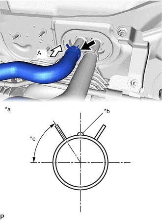
*a View A *b Marking (Green) *c Clip Installation Angle (60°) Connect the water pipe and hose sub-assembly A with the marking facing up and engage the clip within the area shown in the illustration.
Note
Do not apply excessive force to the water pipe and hose sub-assembly A.
-
-
INSTALL OUTER COWL TOP PANEL SUB-ASSEMBLY
-
INSTALL COWL BODY MOUNTING REINFORCEMENT LH
-
INSTALL WATER GUARD PLATE LH
-
INSTALL NO. 1 HEATER AIR DUCT SPLASH SHIELD SEAL (for LHD)
-
INSTALL NO. 2 HEATER AIR DUCT SPLASH SHIELD SEAL (for RHD)
-
INSTALL WINDSHIELD WIPER MOTOR AND LINK ASSEMBLY
-
ADD ENGINE COOLANT (for Engine)
-
INSPECT FOR COOLANT LEAK (for Engine)
-
CHARGE AIR CONDITIONING SYSTEM WITH REFRIGERANT
for HFC-134a (R134a):
for HFO-1234yf (R1234yf):
-
WARM UP COMPRESSOR
for HFC-134a (R134a):
for HFO-1234yf (R1234yf):
-
INSPECT FOR REFRIGERANT LEAK
for HFC-134a (R134a):
for HFO-1234yf (R1234yf):
-
INITIALIZATION SERVO MOTOR