RADIO ANTENNA CORD INSTALLATION
PROCEDURE
-
INSTALL NO. 4 ANTENNA CORD SUB-ASSEMBLY
-
When reusing the No. 4 antenna cord sub-assembly:
-
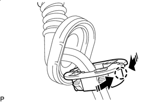

Install in this Direction Engage the claw as shown in the illustration to temporarily install a new No. 1 wire harness protector.
Tech Tips
Use the same procedure for the No. 2 wire harness protector.
-
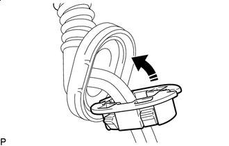
Install in this Direction Install the No. 1 wire harness protector to the grommet as shown in the illustration.
Tech Tips
Use the same procedure for the No. 2 wire harness protector.
-
for Back Door Side:
-
Connect the rubber protrusion of the grommet to the No. 2 wire harness protector with tape.
-
Connect the antenna cord and washer hose to the No. 2 wire harness protector with tape.
-
-
-
Engage the 8 claws to connect the 2 grommets.
-
Engage the clamp.
-
Connect the washer hose.
-
Connect the connector.
-
Engage the 3 clamps.
-
Connect the washer hose.
-
Connect the connector to install the No. 4 antenna cord sub-assembly.
-
-
INSTALL BACK DOOR SIDE GARNISH RH
-
INSTALL BACK DOOR UPPER TRIM PANEL ASSEMBLY
-
INSTALL NO. 3 ANTENNA CORD SUB-ASSEMBLY
-
Engage the 6 clamps.
-
Engage the claw.
-
Connect the connector to install the No. 3 antenna cord sub-assembly.
-
-
INSTALL NO. 5 ANTENNA CORD SUB-ASSEMBLY
-
w/ Digital Audio Broadcasting Antenna or Television Antenna:
-
Engage the clamp.
-
Connect the connector to install the No. 5 antenna cord sub-assembly.
-
-
-
INSTALL NO. 2 ANTENNA CORD SUB-ASSEMBLY
Tech Tips
Butyl tape and adhesive tape are not available as supply parts. If these pieces of tape still have enough adhesion to secure the No. 2 antenna cord sub-assembly to the roof headlining assembly, reuse them. If the adhesive tape and/or the butyl tape is no longer sticky, apply new tape following the procedure below.
-
Apply new butyl tape.
w/o Digital Audio Broadcasting Antenna or Television Antenna:
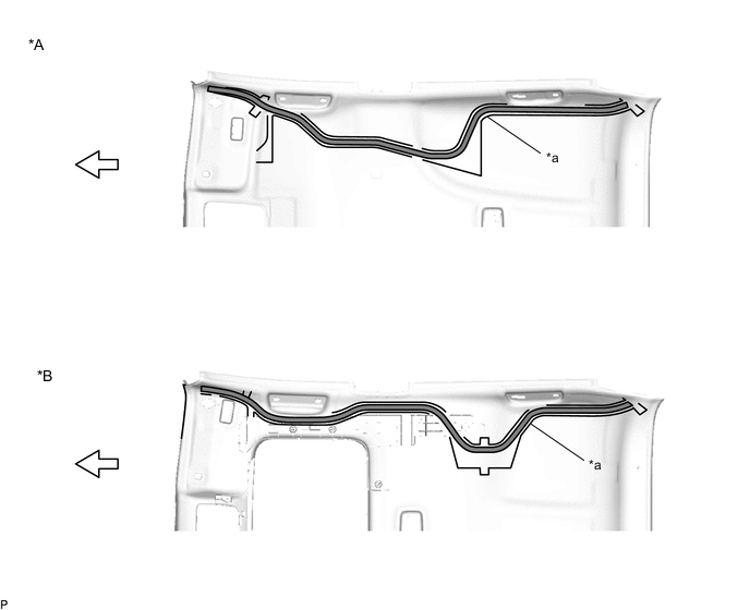
*A w/o Sliding Roof *B w/ Sliding Roof *a Marking - - 
Butyl tape 
Front w/ Digital Audio Broadcasting Antenna or Television Antenna:
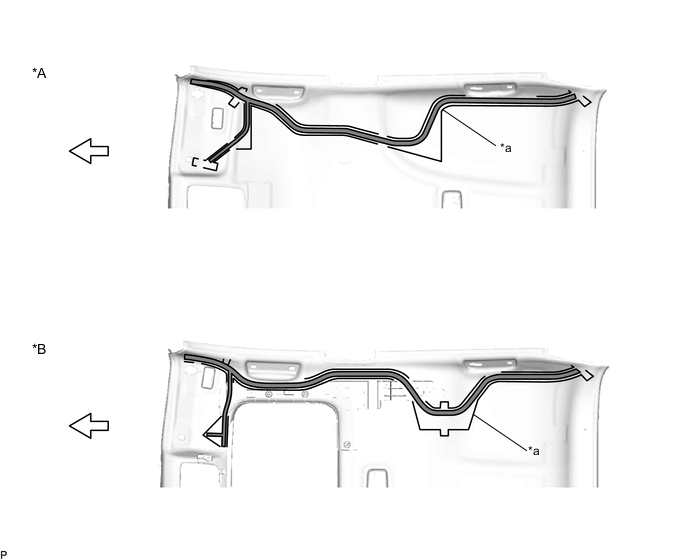
*A w/o Sliding Roof *B w/ Sliding Roof *a Marking - - Butyl tape Front
-
Remove the old butyl tape from the roof headlining assembly.
-
Prepare an appropriate amount of new butyl tape.
Tech Tips
Be careful not to touch the adhesive surface.
-
Apply the butyl tape to the roof headlining assembly while aligning the tape with the markings on the roof headlining assembly.
-
Peel off the release paper from the butyl tape.
-
-
w/o Digital Audio Broadcasting Antenna or Television Antenna:
-
Align the marking tape (A) on the No. 2 antenna cord sub-assembly with the protrusion on the front of the roof headlining assembly and wrap tape around the No. 2 antenna cord sub-assembly and protrusion of the roof headlining assembly.
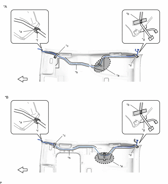
*A w/o Sliding Roof *B w/ Sliding Roof *a Marking Tape (A) *b Marking Tape (B) *c Adhesive Tape (A) *d Adhesive Tape (B) *e Adhesive Tape (C) *f Protrusion *g Notch *h Marking 
Adjustment Area Front -
Install the No. 2 antenna cord sub-assembly to the roof headlining assembly from the marking tape (A) to the adjustment area.
Note
-
Make sure that there are no gaps between the roof headlining assembly and No. 2 antenna cord sub-assembly, and that the No. 2 antenna cord sub-assembly is not twisted.
-
Make sure the No. 2 antenna cord assembly is securely installed. If any part of the No. 2 antenna cord sub-assembly is loose, it will cause an abnormal noise.
-
-
Apply the adhesive tape (A) as shown in the illustration.
-
Engage the No. 2 antenna cord sub-assembly to the notch of the roof headlining assembly.
-
Align the marking tape (B) on the No. 2 antenna cord sub-assembly with the marking on the roof headlining assembly and secure the No. 2 antenna cord sub-assembly with the adhesive tape (B) as shown in the illustration.
-
Install the No. 2 antenna cord sub-assembly to the roof headlining assembly from the marking tape (B) to the adjustment area.
Note
-
Make sure that there are no gaps between the roof headlining assembly and No. 2 antenna cord sub-assembly, and that the No. 2 antenna cord sub-assembly is not twisted.
-
Make sure the No. 2 antenna cord assembly is securely installed. If any part of the No. 2 antenna cord sub-assembly is loose, it will cause an abnormal noise.
Tech Tips
Secure the extra length of the No. 2 antenna cord sub-assembly in the adjustment area.
-
-
Apply the adhesive tape (C) as shown in the illustration to secure the No. 2 antenna cord sub-assembly.
-
-
w/ Digital Audio Broadcasting Antenna or Television Antenna:
-
Align the marking tape (A) on the No. 2 antenna cord sub-assembly with the protrusion on the front of the roof headlining assembly and wrap tape around the No. 2 antenna cord sub-assembly and protrusion of the roof headlining assembly.
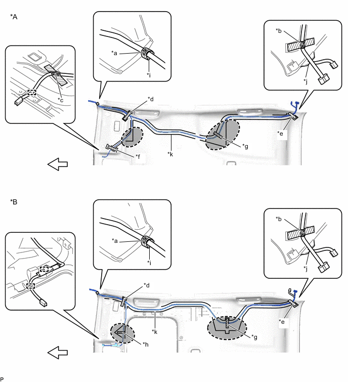
*A w/o Sliding Roof *B w/ Sliding Roof *a Marking Tape (A) *b Marking Tape (B) *c Marking Tape (C) *d Adhesive Tape (A) *e Adhesive Tape (B) *f Adhesive Tape (C) *g Adhesive Tape (D) *h Adhesive Tape (E) *i Protrusion *j Notch *k Marking - - 
Adhesive Tape Front Adjustment Area - - -
Install the No. 2 antenna cord sub-assembly to the roof headlining assembly from the marking tape (A) to each adjustment area.
-
Apply the adhesive tape (A) as shown in the illustration.
-
Engage the No. 2 antenna cord sub-assembly to the notch of the roof headlining assembly.
-
Align the marking tape (B) on the No. 2 antenna cord sub-assembly with the marking on the roof headlining assembly and secure the No. 2 antenna cord sub-assembly with the adhesive tape (B) as shown in the illustration.
-
Install the No. 2 antenna cord sub-assembly to the roof headlining assembly from the marking tape (B) to the adjustment area.
Note
-
Make sure that there are no gaps between the roof headlining assembly and No. 2 antenna cord sub-assembly, and that the No. 2 antenna cord sub-assembly is not twisted.
-
Make sure the No. 2 antenna cord assembly is securely installed. If any part of the No. 2 antenna cord sub-assembly is loose, it will cause an abnormal noise.
Tech Tips
Secure the extra length of the No. 2 antenna cord sub-assembly in the adjustment area.
-
-
w/o Sliding Roof:
-
Align the marking tape (C) on the No. 2 antenna cord sub-assembly with the marking on the roof headlining assembly and secure the No. 2 antenna cord sub-assembly with the adhesive tape (C) as shown in the illustration.
-
-
Install the No. 2 antenna cord sub-assembly to the roof headlining assembly from the marking tape (C) to the adjustment area.
Note
-
Make sure that there are no gaps between the roof headlining assembly and No. 2 antenna cord sub-assembly, and that the No. 2 antenna cord sub-assembly is not twisted.
-
Make sure the No. 2 antenna cord assembly is securely installed. If any part of the No. 2 antenna cord sub-assembly is loose, it will cause an abnormal noise.
Tech Tips
Secure the extra length of the No. 2 antenna cord sub-assembly in the adjustment area.
-
-
Apply the adhesive tape (D) as shown in the illustration to secure the No. 2 antenna cord sub-assembly.
-
Apply the adhesive tape (E) to secure the No. 2 antenna cord sub-assembly. (The adhesive tape (E) is not necessary when the No. 2 antenna cord sub-assembly is installed to butyl tape applied to the roof headlining assembly.)
-
Engage each clamp.
-
-
-
INSTALL ROOF HEADLINING ASSEMBLY
-
INSTALL ANTENNA CORD SUB-ASSEMBLY (for RHD)
-
w/ Navigation Antenna:
-
Engage the 6 clamps to install the antenna cord sub-assembly.
-
-
-
INSTALL ANTENNA CORD SUB-ASSEMBLY
-
for LHD:
-
Engage the 6 clamps to install the antenna cord sub-assembly.
-
-
for RHD:
-
Engage the 4 clamps to install the antenna cord sub-assembly.
-
-
-
INSTALL NO. 3 KNEE PROTECTOR BRACKET (for LHD)
-
INSTALL NO. 2 KNEE PROTECTOR BRACKET (for LHD)
-
INSTALL NO. 2 HEATER TO REGISTER DUCT SUB-ASSEMBLY
-
INSTALL NO. 1 HEATER TO REGISTER DUCT SUB-ASSEMBLY (for RHD)
-
INSTALL LOWER INSTRUMENT PANEL SUB-ASSEMBLY