STEERING COLUMN ASSEMBLY REMOVAL
CAUTION / NOTICE / HINT
The necessary procedures (adjustment, calibration, initialization, or registration) that must be performed after parts are removed, installed, or replaced during the electric power steering column sub-assembly removal/installation are shown below.
| Replacement Part or Procedure | Necessary Procedures | Effects / Inoperative when not performed | Link |
|---|---|---|---|
| Disconnect cable from negative auxiliary battery terminal | Memorize steering angle neutral point | Lane departure alert system (w/ Steering Control) | |
| Intelligent clearance sonar system | |||
| Simple intelligent parking assist system | |||
| Pre-crash safety system | |||
| Parking assist monitor system | |||
| Initialize back door lock | Power door lock control system | ||
| Electric power steering column sub-assembly | Torque sensor zero point calibration |
|
PROCEDURE
-
PRECAUTION
-
ALIGN FRONT WHEELS FACING STRAIGHT AHEAD
-
REMOVE HORN BUTTON ASSEMBLY
-
REMOVE STEERING WHEEL ASSEMBLY
-
REMOVE LOWER STEERING COLUMN COVER SUB-ASSEMBLY
Note
Removing the lower steering column cover sub-assembly in the incorrect order will cause the parts to break.
-
Release the tilt and telescopic lever and fully extend and lower the steering column assembly.
-
Lock the tilt and telescopic lever.
-
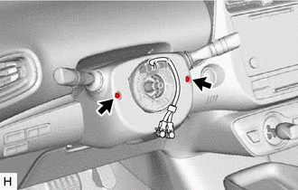
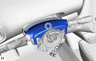
Remove the 2 screws.
-
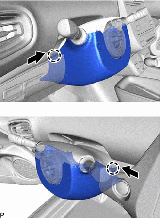

Push Push the upper steering column cover and disengage the 2 claws as shown in the illustration.
-
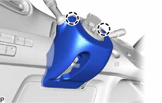
Disengage the 2 claws.
-
Release the tilt and telescopic lever and fully extend and lift the steering column assembly.
-
Lock the tilt and telescopic lever.
-
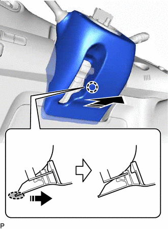

Place Hand Here 
Remove in this Direction Pull the lower steering column cover sub-assembly toward the rear of the vehicle to disengage the claw and remove the lower steering column cover sub-assembly.
-
-
REMOVE UPPER STEERING COLUMN COVER
-
Release the tilt and telescopic lever and fully extend and lower the steering column assembly.
-
Lock the tilt and telescopic lever.
-
Disengage the claw and separate the upper steering column cover.
-
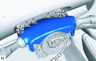
Disengage the 2 claws and 4 clips to remove the upper steering column cover.
-
-
REMOVE TURN SIGNAL SWITCH ASSEMBLY WITH SPIRAL CABLE SUB-ASSEMBLY
Note
-
Do not replace the spiral cable with sensor sub-assembly with the auxiliary battery connected and the power switch on (IG).
-
Do not rotate the spiral cable with sensor sub-assembly without the steering wheel assembly installed with the auxiliary battery connected and the power switch on (IG).
-
Ensure that the steering wheel assembly is installed and aligned straight when inspecting the steering sensor.
-
Disconnect each connector from the turn signal switch assembly with spiral cable sub-assembly.
-
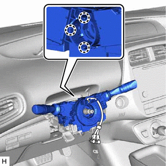
Disengage the 3 claws to remove the turn signal switch assembly with spiral cable sub-assembly from the steering column assembly.
-
-
REMOVE LOWER NO. 1 INSTRUMENT PANEL AIRBAG ASSEMBLY
-
REMOVE REAR CONSOLE BOX ASSEMBLY
-
REMOVE LOWER CENTER INSTRUMENT CLUSTER FINISH PANEL SUB-ASSEMBLY
-
REMOVE FRONT NO. 1 CONSOLE BOX INSERT
-
REMOVE NO. 1 AIR DUCT (for LHD)
-
Remove the 2 bolts.
-
Disengage the 3 claws to remove the No. 1 air duct.
-
-
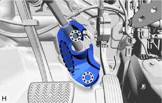
REMOVE PARKING BRAKE MOUNTING BRACKET (for RHD)
-
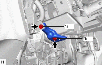
*a Bolt *b Screw Remove the bolt, screw and parking brake mounting bracket.
-
-
REMOVE NO. 2 AIR DUCT (for RHD)
-
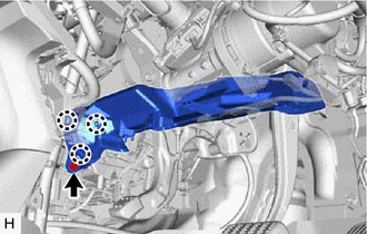
Remove the bolt.
-
Disengage the 3 claws to remove the No. 2 air duct.
-
-
REMOVE STOP LIGHT SWITCH ASSEMBLY
-
REMOVE COLUMN HOLE COVER SILENCER SHEET
-
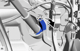
Disengage the claw and open the column hole cover silencer sheet.
-
Place Hand Here Disengage the 2 claws to remove the column hole cover silencer sheet.
-
-
SEPARATE NO. 2 STEERING INTERMEDIATE SHAFT ASSEMBLY
-
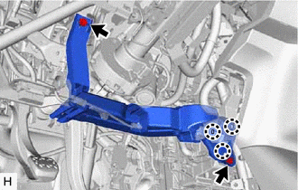
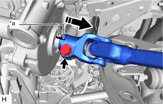
*a Matchmark Separate in this direction Put matchmarks on the No. 2 steering intermediate shaft assembly and steering gear assembly.
-
Remove the bolt.
-
Separate the No. 2 steering intermediate shaft assembly from the steering gear assembly.
-
-
REMOVE NO. 2 STEERING INTERMEDIATE SHAFT ASSEMBLY
-
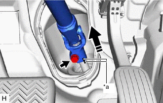
*a Matchmark Remove in this direction Put matchmarks on the No. 2 steering intermediate shaft assembly and steering column assembly.
-
Remove the bolt.
-
Remove the No. 2 steering intermediate shaft assembly from the steering column assembly.
-
-
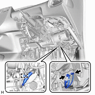
REMOVE STEERING COLUMN ASSEMBLY (for LHD)
-
Disconnect the 2 connectors.
-
Disengage the clamp.
-
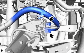
Disconnect each connector and disengage each clamp from the steering column assembly.
-
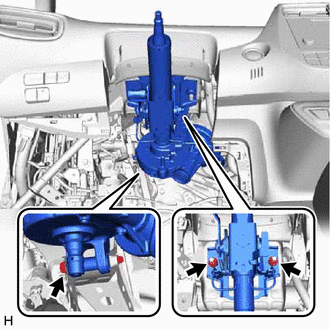
Remove the bolt, 2 nuts and steering column assembly.
-
-
REMOVE STEERING COLUMN ASSEMBLY (for RHD)
-
Disconnect the 2 connectors.
-
Disengage the clamp.
-
Disconnect each connector and disengage each clamp from the steering column assembly.
-
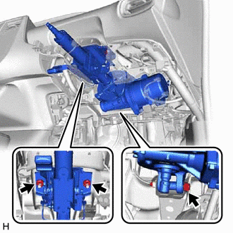
Remove the bolt, 2 nuts and steering column assembly.
-