BRAKE PEDAL STROKE SENSOR(for RHD) INSTALLATION
PROCEDURE
-
INSPECT AND ADJUST BRAKE PEDAL HEIGHT
-
INSTALL BRAKE PEDAL STROKE SENSOR ASSEMBLY
Note
-
Do not drop the brake pedal stroke sensor assembly.
-
If the brake pedal stroke sensor assembly has been dropped, replace the brake pedal stroke sensor assembly with a new one.
-
When installing a new brake pedal stroke sensor assembly:
Note
Do not break the brake pedal stroke sensor assembly lever set pin before installing the brake pedal stroke sensor assembly with the 2 nuts.
-
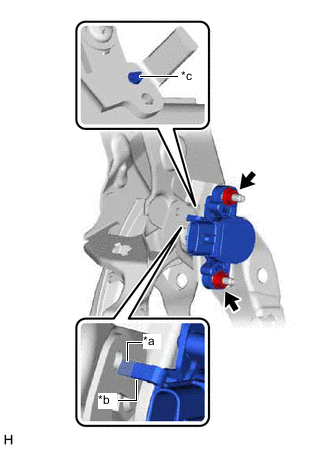
*a Brake Pedal Stroke Sensor Assembly Lever *b Brake Pedal Groove *c Brake Pedal Stroke Sensor Assembly Lever Set Pin Install a new brake pedal stroke sensor assembly to the brake pedal support assembly with the 2 nuts.
- Torque:
- 8.5 N*m { 87 kgf*cm, 75 in.*lbf }
Note
-
Engage the brake pedal stroke sensor assembly lever with the brake pedal groove.
-
Check that there is no foreign matter attached to the contact surface of the brake pedal stroke sensor assembly.
-
Check that the tip of the brake pedal stroke sensor assembly lever is protruding from the brake pedal groove.
-
Connect the connector.
-
Firmly depress the brake pedal to break the brake pedal stroke sensor assembly lever set pin.
-
Remove the broken lever set pin.
-
-
When reusing the brake pedal stroke sensor assembly:
-
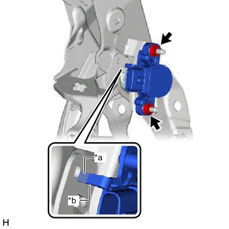
*a Brake Pedal Stroke Sensor Assembly Lever *b Brake Pedal Groove Install the brake pedal stroke sensor assembly to the brake pedal support assembly and temporarily tighten the 2 nuts.
Note
-
Engage the brake pedal stroke sensor assembly lever with the brake pedal groove.
-
Check that there is no foreign matter attached to the contact surface of the brake pedal stroke sensor assembly.
-
Check that the tip of the brake pedal stroke sensor assembly lever is protruding from the brake pedal groove.
-
-
Connect the connector.
-
-
-
INSTALL LOWER INSTRUMENT PANEL FINISH PANEL ASSEMBLY
-
CONNECT HOOD LOCK CONTROL LEVER SUB-ASSEMBLY
-
INSTALL INSTRUMENT CLUSTER FINISH PANEL GARNISH ASSEMBLY
-
CONNECT CABLE TO NEGATIVE AUXILIARY BATTERY TERMINAL
-
ADJUST BRAKE PEDAL STROKE SENSOR ASSEMBLY
Note
When the brake pedal stroke sensor assembly is being reused, perform the following procedure to adjust it.
-
Connect the GTS to the DLC3 with the power switch off.
-
Turn the power switch on (IG).
-
Turn the GTS on.
-
Enter the following menus: Chassis / ABS/VSC/TRC / Data List / Stroke Sensor.
Chassis > ABS/VSC/TRC > Data ListTester Display Stroke Sensor -
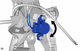
Read the stroke sensor value in the Data List, and turn the brake pedal stroke sensor assembly slowly to the right or left to adjust the output voltage so that it is within the following range.
Standard Voltage (without the brake pedal depressed) 0.8 to 1.2 V -
Tighten the 2 nuts.
- Torque:
- 8.5 N*m { 87 kgf*cm, 75 in.*lbf }
Note
Do not depress the brake pedal after turning the power switch on (IG).
-
Turn the GTS off and turn the power switch off.
-
Disconnect the GTS from the DLC3.
-
-
INSTALL INSTRUMENT PANEL FINISH PANEL END RH
-
INSTALL NO. 1 INSTRUMENT PANEL UNDER COVER SUB-ASSEMBLY
-
INSTALL COWL SIDE TRIM BOARD RH
-
INSTALL FRONT DOOR SCUFF PLATE RH
-
PERFORM INITIALIZATION AND CALIBRATION
Perform linear solenoid valve offset learning, ABS holding solenoid valve learning, brake pedal stroke sensor assembly zero point calibration and system information memorization: Click here
-
CHECK AND CLEAR DTC