BRAKE PEDAL(for LHD) INSTALLATION
PROCEDURE
-
INSTALL BRAKE PEDAL PAD
-
Install the brake pedal pad from the brake pedal support assembly.
-
-
INSTALL BRAKE PEDAL SUPPORT ASSEMBLY
-
Install the nut to the brake pedal support assembly.
-

Nut 
Clip Temporarily install the brake pedal support assembly with 2 new clips.
-
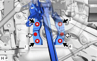
Install the 4 nuts.
- Torque:
- 12.7 N*m { 130 kgf*cm, 9 ft.*lbf }
Note
Tighten the nuts in the order shown in the illustration.
-
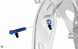
Install the brake pedal support assembly to the instrument panel reinforcement assembly with the bolt.
- Torque:
- 23.6 N*m { 241 kgf*cm, 17 ft.*lbf }
-
Engage the clamp to install the wire harness to the brake pedal support assembly.
-
-
INSTALL PUSH ROD PIN
-
Lithium soap base glycol grease Apply lithium soap base glycol grease to the push rod pin and installation hole of the brake pedal support assembly.
-
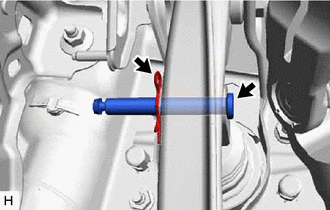
Connect the brake master cylinder push rod clevis to the brake pedal support assembly with the push rod pin, and install a new clip as shown in the illustration.
Note
Be sure to install the push rod pin in the correct direction.
-
-
INSTALL BRAKE PEDAL RETURN SPRING
-
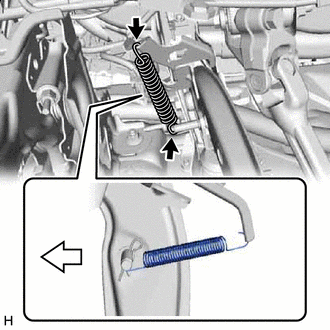
Front Install the brake pedal return spring to the brake pedal support assembly and push rod pin as shown in the illustration.
-
-
INSTALL STOP LIGHT SWITCH MOUNTING ADJUSTER
-
INSTALL STOP LIGHT SWITCH ASSEMBLY
-
INSTALL BRAKE PEDAL STROKE SENSOR ASSEMBLY
-
INSTALL LOWER INSTRUMENT PANEL SUB-ASSEMBLY
-
INSPECT AND ADJUST BRAKE PEDAL