EGR VALVE REMOVAL

CAUTION / NOTICE / HINT
The necessary procedures (adjustment, calibration, initialization or registration) that must be performed after parts are removed and installed, or replaced during EGR valve assembly removal/installation are shown below.
| Replaced Part or Performed Procedure | Necessary Procedures | Effect/Inoperative Function when Necessary Procedure not Performed | Link |
|---|---|---|---|
| Auxiliary battery terminal is disconnected/reconnected | Memorize steering angle neutral point | Lane departure alert system (w/ Steering Control System) | |
| Intelligent clearance sonar system*1 | |||
| Simple advanced parking guidance system*1 | |||
| Pre-crash safety system | |||
| Parking assist monitor system | |||
| Initialize back door lock | Power door lock control system | ||
| Replacement of inverter with converter assembly | Resolver learning |
|
|
| Replacement of EGR valve assembly | Inspection After Repair |
|
Click here w/ Canister Pump Module Click here w/o Canister Pump Module |
*1: When performing learning using the GTS.
CAUTION:
-
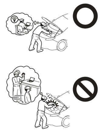
Orange wire harnesses and connectors indicate high-voltage circuits. To prevent electric shock, always follow the procedure described in the repair manual.
-
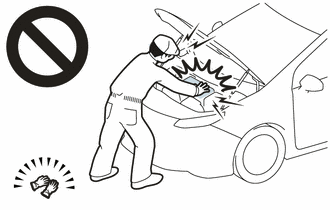
To prevent electric shock, wear insulated gloves when working on wire harnesses and components of the high voltage system.
PROCEDURE
-
PRECAUTION
Note
After turning the power switch off, waiting time may be required before disconnecting the cable from the negative (-) auxiliary battery terminal. Therefore, make sure to read the disconnecting the cable from the negative (-) auxiliary battery terminal notices before proceeding with work.
-
REMOVE SERVICE PLUG GRIP
-
REMOVE REAR MOTOR UNDER COVER LH
-
DRAIN ENGINE COOLANT (for Engine)
-
DISCONNECT ENGINE WIRE
-
REMOVE AUXILIARY BATTERY
-
REMOVE WINDSHIELD WIPER MOTOR AND LINK ASSEMBLY
-
REMOVE NO. 1 HEATER AIR DUCT SPLASH SHIELD SEAL (for LHD)
-
REMOVE NO. 2 HEATER AIR DUCT SPLASH SHIELD SEAL (for RHD)
-
REMOVE WATER GUARD PLATE LH
-
REMOVE COWL BODY MOUNTING REINFORCEMENT LH
-
REMOVE OUTER COWL TOP PANEL SUB-ASSEMBLY
-
REMOVE NO. 1 ENGINE COVER SUB-ASSEMBLY
-
REMOVE BATTERY CLAMP SUB-ASSEMBLY
-
DISCONNECT ENGINE WIRE
CAUTION:
Wear insulated gloves.
Note
Do not allow any foreign matter or water to enter the inverter with converter assembly.
-
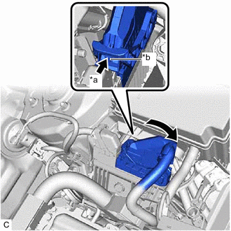
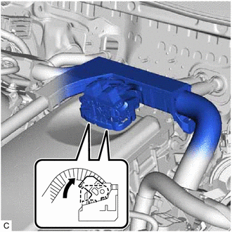
*a Push *b Lock Raise the lever while pushing the lock on the lever, and disconnect the ECM connector.
Note
After disconnecting the ECM connector, make sure that dirt, water or other foreign matter does not contact the connecting parts of the ECM connector.
-
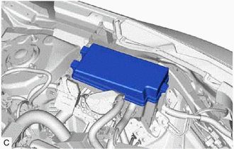
Remove the No. 1 relay block cover.
-
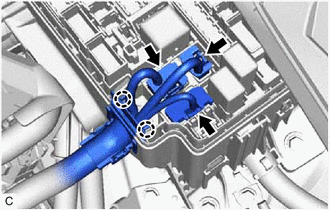
Disconnect the 3 No. 1 engine room relay block and No. 1 junction block assembly connectors.
-
Disengage the 2 claws.
-
Move the 2 lock levers as shown in the illustration and disconnect the 2 inverter with converter assembly connectors.
Note
-
Do not damage the terminals, connector housing or inverter with converter assembly during disconnection.
-
Cover the hole where the cable was connected with tape (non-residue type) or equivalent to prevent entry of foreign matter.
-
Do not allow any foreign matter or water to enter the inverter with converter assembly.
-
Insulate the disconnected terminals with insulating tape.
-
Do not touch the waterproof seal or terminals of the connector.
-
-
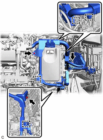
Remove the 3 bolts.
-
Disengage the 4 clamps and disconnect the engine wire.
-
-
REMOVE CONNECTOR COVER ASSEMBLY
-
CHECK TERMINAL VOLTAGE
-
TEMPORARILY INSTALL CONNECTOR COVER ASSEMBLY
-
DISCONNECT HV FLOOR UNDER WIRE
-
DISCONNECT AIR CONDITIONING WIRE
-
SEPARATE INVERTER WITH CONVERTER ASSEMBLY
CAUTION:
Wear insulated gloves.
-
Remove the 5 bolts and 2 nuts and separate the inverter with converter assembly.
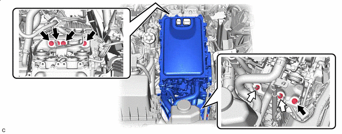

Bolt 
Nut Note
-
To prevent damage due to static electricity, do not touch the terminals of the inverter with converter assembly connector.
-
Make sure to seal the inverter with converter assembly with the connector cover assembly or tape (non-residue type) etc., to prevent entry of foreign matter and water.
-
-
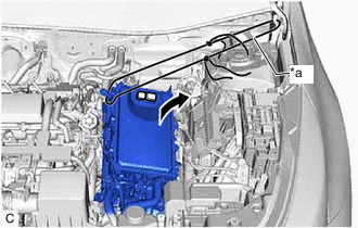
*a Rope Using a rope or equivalent, secure the inverter with converter assembly with the hood hinge.
Note
-
Be careful not to damage the surrounding components when securing the inverter with converter assembly.
-
To prevent damage to the inverter with converter assembly, do not hold the coolant pipe, bracket or connector when securing the inverter with converter assembly.
-
To prevent damage due to static electricity, do not touch the terminals of the inverter with converter assembly connector.
-
Make sure to seal the inverter with converter assembly with the connector cover assembly or tape (non-residue type) etc., to prevent entry of foreign matter and water.
-
-
-
REMOVE EGR PIPE ASSEMBLY
-
REMOVE EGR VALVE ASSEMBLY
-
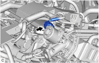
Disconnect the EGR valve assembly connector.
-
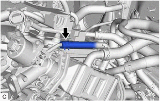
Slide the clip and disconnect the No. 6 water by-pass hose from the EGR valve assembly.
-
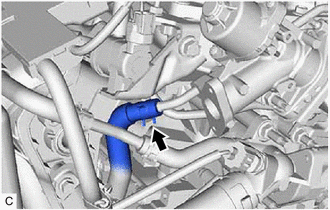
Slide the clip and disconnect the water by-pass hose assembly from the EGR valve assembly.
-
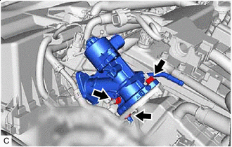
Remove the 3 nuts.
-
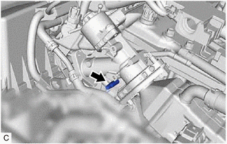
Using an E8 "TORX" socket wrench, remove the stud bolt from the camshaft housing sub-assembly.
Tech Tips
If a stud bolt is deformed or the threads are damaged, replace it.
-
Remove the EGR valve assembly from the EGR pipe with cooler sub-assembly.
-
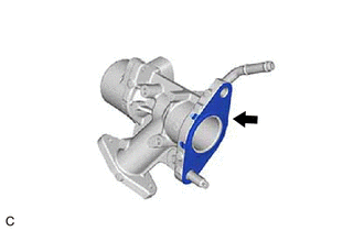
Remove the EGR valve gasket from the EGR valve assembly.
-