CYLINDER HEAD GASKET REMOVAL
CAUTION / NOTICE / HINT
The necessary procedures (adjustment, calibration, initialization, or registration) that must be performed after parts are removed and installed, or replaced during cylinder head gasket removal/installation are shown below.
| Replaced Part or Performed Procedure | Necessary Procedure | Effect/Inoperative Function when Necessary Procedure not Performed | Link |
|---|---|---|---|
| Auxiliary battery terminal is disconnected/reconnected | Memorize steering angle neutral point | Lane departure alert system (w/ Steering Control) | |
| Intelligent clearance sonar system*1 | |||
| Simple intelligent parking assist system*1 | |||
| Pre-crash safety system | |||
| Parking assist monitor system | |||
| Initialize back door lock | Power door lock control system | ||
| Replacement of inverter with converter assembly | Resolver learning |
|
|
for SFI system (w/ Canister Pump Module) |
Perform Vehicle Identification Number (VIN) registration | MIL comes on | |
for SFI system (w/o Canister Pump Module) |
Perform Vehicle Identification Number (VIN) or frame number registration | ||
for SFI system (w/ Canister Pump Module) |
Inspection After Repair |
|
|
for SFI system (w/o Canister Pump Module) |
Inspection After Repair |
|
|
| Suspension, tires, etc. (The vehicle height changes because of suspension or tire replacement) |
|
|
|
| Rear television camera assembly optical axis (Back camera position setting) | Parking assist monitor system | ||
| Initialize No. 1 headlight ECU sub-assembly LH | Automatic headlight beam level control system | ||
| Front wheel alignment adjustment |
|
|
|
| Replacement of hybrid vehicle transaxle assembly |
|
|
*1: When performing learning using the GTS.
PROCEDURE
-
INSTALL ENGINE TO ENGINE STAND
-
REMOVE ENGINE HANGERS
-
REMOVE WATER OUTLET (w/ Flow Shutting Valve (Water Valve))
-
REMOVE WATER OUTLET (w/o Flow Shutting Valve (Water Valve))
-
REMOVE EGR PIPE ASSEMBLY
-
REMOVE EGR VALVE ASSEMBLY WITH EGR COOLER
-
REMOVE NO. 1 EXHAUST MANIFOLD HEAT INSULATOR
-
REMOVE MANIFOLD STAY
-
REMOVE EXHAUST MANIFOLD (TWC: Front Catalyst)
-
REMOVE INTAKE MANIFOLD
-
REMOVE ENGINE OIL LEVEL DIPSTICK
-
REMOVE ENGINE OIL LEVEL DIPSTICK GUIDE
-
REMOVE NO. 5 WATER BY-PASS PIPE (w/ Exhaust Heat Recirculation System)
-
REMOVE NO. 6 WATER BY-PASS PIPE
-
REMOVE PURGE VALVE (PURGE VSV)
-
REMOVE FUEL VAPOR FEED PIPE
-
REMOVE FUEL DELIVERY PIPE SUB-ASSEMBLY
-
REMOVE NO. 1 DELIVERY PIPE SPACER
-
REMOVE FUEL INJECTOR ASSEMBLY
-
REMOVE IGNITION COIL ASSEMBLY
-
REMOVE CAMSHAFT POSITION SENSOR
-
REMOVE CYLINDER HEAD COVER SUB-ASSEMBLY
-
REMOVE CYLINDER HEAD COVER GASKET
-
REMOVE SPARK PLUG TUBE GASKET
-
SET NO. 1 CYLINDER TO TDC (COMPRESSION)
-
REMOVE CRANKSHAFT PULLEY
-
REMOVE NO. 1 CHAIN TENSIONER ASSEMBLY
-
REMOVE TIMING CHAIN COVER OIL SEAL
-
REMOVE TIMING CHAIN COVER SUB-ASSEMBLY
-
REMOVE CHAIN TENSIONER SLIPPER
-
REMOVE NO. 1 CHAIN VIBRATION DAMPER
-
REMOVE NO. 2 CHAIN VIBRATION DAMPER
-
REMOVE CHAIN SUB-ASSEMBLY
-
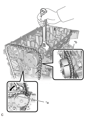
*a Loosen the chain sub-assembly *b Place the chain sub-assembly on the non-toothed portion of camshaft timing gear assembly Using a wrench to hold the hexagonal portion of the camshaft, turn the camshaft timing gear assembly counterclockwise to loosen the chain sub-assembly between the camshaft timing sprocket and camshaft timing gear assembly.
-
With the chain sub-assembly loosened, separate the chain sub-assembly from the teeth of the camshaft timing gear assembly and place it on the non-toothed portion of camshaft timing gear assembly.
-
Turn the camshaft clockwise to return it to its original position and remove the chain sub-assembly.
-
-
INSPECT CAMSHAFT TIMING GEAR ASSEMBLY
-
REMOVE CAMSHAFT TIMING GEAR ASSEMBLY
-
REMOVE CAMSHAFT TIMING SPROCKET
-
REMOVE CAMSHAFT BEARING CAP
-
REMOVE NO. 2 CAMSHAFT
-
REMOVE CAMSHAFT
-
REMOVE CAMSHAFT HOUSING SUB-ASSEMBLY
-
REMOVE NO. 1 VALVE ROCKER ARM SUB-ASSEMBLY
-
REMOVE VALVE LASH ADJUSTER ASSEMBLY
-
REMOVE VALVE STEM CAP
-
REMOVE CYLINDER HEAD SUB-ASSEMBLY
-
REMOVE CYLINDER HEAD GASKET
-
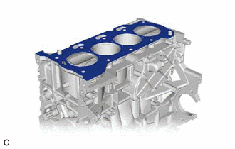
Remove the cylinder head gasket from the cylinder block sub-assembly.
-
-
INSPECT CYLINDER HEAD SET BOLT