SFI SYSTEM(w/ Canister Pump Module), Diagnostic DTC:P050B00
| DTC Code | DTC Name |
|---|---|
| P050B00 | Cold Start Ignition Timing Performance |
MONITOR DESCRIPTION
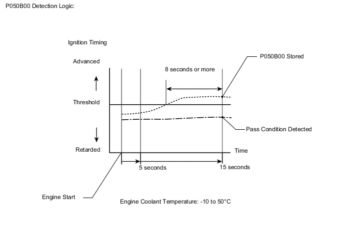
A monitor will run when the engine is started at an engine coolant temperature of -10 to 50°C (14 to 122°F). If certain conditions are met, a DTC is stored after the engine idles for 15 seconds (2 trip detection logic).
This DTC is designed to monitor the ignition timing at cold start. When the engine is started at an engine coolant temperature of less than 50°C (122°F), the ECM checks the ignition timing during engine idling. If the ignition timing advances beyond the specified level within 10 seconds, the ECM interprets this as a malfunction, illuminates the MIL and stores this DTC.
Note
The idle speed control learned values are cleared by performing learning value reset. Idle speed control learning needs to be performed before this DTC can be stored.
| DTC No. | Detection Item | DTC Detection Condition | Trouble Area | MIL | Memory | Note |
|---|---|---|---|---|---|---|
| P050B00 | Cold Start Ignition Timing Performance | Ignition timing insufficiently retarded at cold start (2 trip detection logic). |
|
Comes on | DTC stored | SAE Code: P050B |
MONITOR STRATEGY
| Required Sensors/Components (Main) | Throttle body assembly |
| Required Sensors/Components (Related) | Engine coolant temperature sensor Mass air flow meter sub-assembly |
| Frequency of Operation | Once per driving cycle |
TYPICAL MALFUNCTION THRESHOLDS
| Accumulated time when ignition timing retard is cut off | 8 seconds or more |
CONFIRMATION DRIVING PATTERN
-
Connect the GTS to the DLC3.
-
Turn the power switch on (IG).
-
Turn the GTS on.
-
Clear the DTCs (even if no DTCs are stored, perform the clear DTC procedure).
-
Turn the power switch off and wait for at least 30 seconds.
-
Turn the power switch on (IG).
-
Turn the GTS on.
-
Put the engine in Inspection Mode (Maintenance Mode).
-
Start the engine and warm it up for 5 minutes or more.
-
Stop the engine.
-
Leave the vehicle outside overnight.
-
Turn the power switch on (IG) [A].
-
Turn the GTS on.
-
Enter the following menus: Powertrain / Engine / Data List / Coolant Temperature.
-
Check that the value of the Data List item Coolant Temperature is between -10 and 50°C (14 and 122°F).
-
Put the engine in Inspection Mode (Maintenance Mode).
-
Start the engine and warm it up until the engine coolant temperature is the same as the coolant temperature in the freeze frame data.
-
Idle the engine for 1 minute or more [B].
-
Enter the following menus: Powertrain / Engine / Trouble Codes.
-
Read the pending DTC.
Tech Tips
-
If a pending DTC is output, the system is malfunctioning.
-
If a pending DTC is not output, perform the following procedure.
-
-
Enter the following menus: Powertrain / Engine / Utility / All Readiness.
-
Input the DTC: P050B00.
-
Check the DTC judgment result.
GTS Display Description NORMAL
-
DTC judgment completed
-
System normal
ABNORMAL
-
DTC judgment completed
-
System abnormal
INCOMPLETE
-
DTC judgment not completed
-
Perform driving pattern after confirming DTC enabling conditions
N/A
-
Unable to perform DTC judgment
-
Number of DTCs which do not fulfill DTC preconditions has reached ECU memory limit
Tech Tips
-
If the judgment result is NORMAL, the system is normal.
-
If the judgment result is ABNORMAL, the system is malfunctioning.
-
If the judgment result is INCOMPLETE or N/A, idle the engine for 3 minutes, let the engine cool down, and then perform steps [A] and [B].
-
CAUTION / NOTICE / HINT
Note
Inspect the fuses for circuits related to this system before performing the following procedure.
Tech Tips
-
DTC P050B00 may be set when the engine has the symptoms listed below. If necessary, check the trouble areas listed below.
Symptoms Factor Trouble Area Low idle speed when engine is cold
(immediately after engine start)
Excessive engine friction
-
Engine oil deterioration
-
Drive belt tension
Rough idle when engine is cold
(immediately after engine start)
Abnormal combustion Fuel quality -
-
Read freeze frame data using the GTS. The ECM records vehicle and driving condition information as freeze frame data the moment a DTC is stored. When troubleshooting, freeze frame data can be helpful in determining whether the vehicle was moving or stationary, whether the engine was warmed up or not, whether the air fuel ratio was lean or rich, as well as other data recorded at the time of a malfunction.
PROCEDURE
-
CHECK ANY OTHER DTCS OUTPUT (IN ADDITION TO DTC P050B00)
-
Connect the GTS to the DLC3.
-
Turn the power switch on (IG).
-
Turn the GTS on.
-
Enter the following menus: Powertrain / Engine / Trouble Codes.
-
Read the DTCs.
Powertrain > Engine > Trouble CodesResult Result Proceed to DTC P050B00 is output A DTC P050B00 and other DTCs are output B Tech Tips
If any DTCs other than P050B00 are output, troubleshoot those DTCs first.
B 
GO TO DTC CHART Click here
A 
-
-
READ VALUE USING GTS (FUEL TRIM)
Tech Tips
Calculate the total fuel trim values to check the characteristic deviation of the mass air flow meter sub-assembly.
-
Connect the GTS to the DLC3.
-
Turn the power switch on (IG).
-
Turn the GTS on.
-
Put the engine in Inspection Mode (Maintenance Mode).
Powertrain > Hybrid Control > UtilityTester Display Inspection Mode -
Start the engine.
-
Enter the following menus: Powertrain / Engine / Data List / Short FT Bank 1 and Long FT Bank 1.
Powertrain > Engine > Data ListTester Display Short FT Bank 1 Long FT Bank 1 -
Read the values displayed on the GTS at engine idle.
-
Add the Short FT Bank 1 and Long FT Bank 1 values to obtain the total fuel trim.
Standard Total of Short FT Bank 1 and Long FT Bank 1 values is between -20 and 20%. Result Proceed to OK NG
NG 
CHECK PCV HOSE CONNECTIONS Click here
OK
-
-
INSPECT THROTTLE BODY ASSEMBLY (VISUALLY CHECK THROTTLE VALVE)
-
Check for foreign matter between the throttle valve and housing. If necessary, clean the throttle body assembly. Also, check that the throttle valve moves smoothly.
OK Throttle valve is not contaminated with foreign matter and moves smoothly. Result Proceed to OK NG
NG
REPLACE THROTTLE BODY ASSEMBLY Click here
OK
-
-
PERFORM ACTIVE TEST USING GTS (CONTROL THE EGR STEP POSITION)
-
Connect the GTS to the DLC3.
-
Turn the power switch on (IG).
-
Turn the GTS on.
-
Put the engine in Inspection Mode (Maintenance Mode).
Powertrain > Hybrid Control > UtilityTester Display Inspection Mode -
Start the engine and warm it up until the engine coolant temperature is 75°C (167°F) or higher.
Tech Tips
The A/C switch and all accessories should be off.
-
Enter the following menus: Powertrain / Engine / Active Test / Control the EGR Step Position / Data List / Intake Manifold Absolute Pressure, EGR Step Position and Engine Independent.
Powertrain > Engine > Active TestActive Test Display Control the EGR Step Position Data List Display Intake Manifold Absolute Pressure EGR Step Position Engine Independent -
Confirm that the value of Data List item Engine Independent is "Operate" then check the value of Intake Manifold Absolute Pressure while performing the Active Test.
Note
-
Do not leave the EGR valve open for 10 seconds or more during the Active Test.
-
Be sure to return the EGR valve to step 0 when the Active Test is completed.
-
Do not open the EGR valve 30 steps or more during the Active Test.
OK The value of Intake Manifold Absolute Pressure changes in response to the EGR step position when the value of Engine Independent is "Operate". Standard - Control the EGR Step Position (Active Test) 0 Steps 0 to 30 Steps Intake Manifold Absolute Pressure
(Data List)
(EGR valve is fully closed) Intake Manifold Absolute Pressure value is at least +10 kPa (1.45 psi) higher than when EGR valve is fully closed Tech Tips
-
If the value of Data List item Engine Independent is "Not Opr" when the engine is idling, charge control is being performed. Perform the Active Test after charge control is complete ("Operate" is displayed).
-
While performing the Active Test, if the increase in the value of Intake Manifold Absolute Pressure is small, the EGR valve assembly may be malfunctioning.
-
Even if the EGR valve assembly is malfunctioning, rough idling or an increase in the value of Intake Manifold Absolute Pressure may occur while performing the Active Test. However, the amount that the value of Intake Manifold Absolute Pressure increases will be smaller than normal.
Result Result Proceed to The value of Intake Manifold Absolute Pressure increases by 10 kPa(abs) or more, compared to when the EGR valve was fully closed (0 step) OK Other than above NG Tech Tips
10 kPa = 1.45 psi
-
OK
GO TO STEP 14 Click here
NG
-
-
INSPECT EGR VALVE ASSEMBLY
-
Remove the EGR valve assembly.
Tech Tips
-
Check if the EGR valve is stuck open.
OK EGR valve is tightly closed. Result Proceed to OK NG
OK
GO TO STEP 14 Click here
NG
GO TO STEP 25 Click here
-
-
REPLACE THROTTLE BODY ASSEMBLY
-
Replace the throttle body assembly.
Tech Tips
-
Perform "Inspection After Repair" after replacing the throttle body assembly.
Result Proceed to NEXT
NEXT
GO TO STEP 29 Click here
-
-
CHECK PCV HOSE CONNECTIONS
-
Check the PCV hose connections.
Tech Tips
OK PCV valve and hose are connected correctly and are not damaged. Result Proceed to OK NG
NG
REPAIR OR REPLACE PCV HOSE Click here
OK
-
-
CHECK INTAKE SYSTEM
-
Check the intake system for vacuum leaks.
OK No leaks from intake system. Result Proceed to OK NG
NG
REPAIR OR REPLACE INTAKE SYSTEM Click here
OK
-
-
CHECK AIR CLEANER FILTER ELEMENT SUB-ASSEMBLY
-
Visually check that the air cleaner filter element sub-assembly is not excessively contaminated with dirt or oil.
OK The air cleaner filter element sub-assembly is not excessively contaminated with dirt or oil. Result Proceed to OK NG
NG
REPLACE AIR CLEANER FILTER ELEMENT SUB-ASSEMBLY Click here
OK
-
-
PERFORM ACTIVE TEST USING GTS (CONTROL THE EGR STEP POSITION)
-
Connect the GTS to the DLC3.
-
Turn the power switch on (IG).
-
Turn the GTS on.
-
Put the engine in Inspection Mode (Maintenance Mode).
Powertrain > Hybrid Control > UtilityTester Display Inspection Mode -
Start the engine and warm it up until the engine coolant temperature is 75°C (167°F) or higher.
Tech Tips
The A/C switch and all accessories should be off.
-
Enter the following menus: Powertrain / Engine / Active Test / Control the EGR Step Position / Data List / Intake Manifold Absolute Pressure, EGR Step Position and Engine Independent.
Powertrain > Engine > Active TestActive Test Display Control the EGR Step Position Data List Display Intake Manifold Absolute Pressure EGR Step Position Engine Independent -
Confirm that the value of Data List item Engine Independent is "Operate" then check the value of Intake Manifold Absolute Pressure while performing the Active Test.
Note
-
Do not leave the EGR valve open for 10 seconds or more during the Active Test.
-
Be sure to return the EGR valve to step 0 when the Active Test is completed.
-
Do not open the EGR valve 30 steps or more during the Active Test.
OK The value of Intake Manifold Absolute Pressure changes in response to the EGR step position when the value of Engine Independent is "Operate". Standard - Control the EGR Step Position (Active Test) 0 Steps 0 to 30 Steps Intake Manifold Absolute Pressure
(Data List)
(EGR valve is fully closed) Intake Manifold Absolute Pressure value is at least +10 kPa (1.45 psi) higher than when EGR valve is fully closed Tech Tips
-
If the value of Data List item Engine Independent is "Not Opr" when the engine is idling, charge control is being performed. Perform the Active Test after charge control is complete ("Operate" is displayed).
-
While performing the Active Test, if the increase in the value of Intake Manifold Absolute Pressure is small, the EGR valve assembly may be malfunctioning.
-
Even if the EGR valve assembly is malfunctioning, rough idling or an increase in the value of Intake Manifold Absolute Pressure may occur while performing the Active Test. However, the amount that the value of Intake Manifold Absolute Pressure increases will be smaller than normal.
Result Result Proceed to The value of Intake Manifold Absolute Pressure increases by 10 kPa(abs) or more, compared to when the EGR valve was fully closed (0 step) OK Other than above NG Tech Tips
10 kPa = 1.45 psi
-
OK
GO TO STEP 12 Click here
NG
-
-
INSPECT EGR VALVE ASSEMBLY
-
Remove the EGR valve assembly.
Tech Tips
-
Check if the EGR valve is stuck open.
OK EGR valve is tightly closed. Result Proceed to OK NG
NG
REPLACE EGR VALVE ASSEMBLY Click here
OK
-
-
PERFORM ACTIVE TEST USING TECHSTREAM (CONTROL THE INTAKE VVT OCV DUTY RATIO BANK 1)
-
Connect the GTS to the DLC3.
-
Turn the power switch on (IG).
-
Turn the GTS on.
-
Put the engine in Inspection Mode (Maintenance Mode).
Powertrain > Hybrid Control > UtilityTester Display Inspection Mode -
Start the engine.
-
Enter the following menus: Powertrain / Engine / Active Test / Control the Intake VVT OCV Duty Ratio Bank 1 / Data List / Intake VVT Change Angle Bank 1.
Powertrain > Engine > Active TestActive Test Display Control the Intake VVT OCV Duty Ratio Bank 1 Data List Display Intake VVT Change Angle Bank 1 -
Read the Data List while performing the Active Test with the engine idling.
OK GTS Operation Data List (Intake VVT Change Angle Bank 1) -100% to 100% Varies by 70 DegFR or more Tech Tips
-
Test not possible with park (P) selected during charge control. Select neutral (N) to perform test.
-
If DTCs are stored after the Active Test, clear the DTCs.
Result Result Proceed to The value of Intake VVT Change Angle Bank 1 is 70 DegFR or more OK Other than above NG -
NG
INSPECT CAMSHAFT TIMING OIL CONTROL VALVE ASSEMBLY Click here
OK
-
-
READ VALUE USING GTS (MASS AIR FLOW SENSOR)
-
Connect the GTS to the DLC3.
-
Turn the power switch on (IG).
-
Turn the GTS on.
-
Put the engine in Inspection Mode (Maintenance Mode).
Powertrain > Hybrid Control > UtilityTester Display Inspection Mode -
Start the engine.
-
Enter the following menus: Powertrain / Engine / Data List / Engine Speed, Mass Air Flow Sensor and Coolant Temperature.
Powertrain > Engine > Data ListTester Display Engine Speed Mass Air Flow Sensor Coolant Temperature -
Allow the engine to idle until Coolant Temperature is 75°C (167°F) or higher.
-
Read Mass Air Flow Sensor with the engine speed at 2500 rpm.
Tech Tips
During charge control, the engine speed is set at idle. Therefore, the engine speed will not increase when the accelerator pedal is depressed. In this case, read the Data List after charge control has completed.
Standard GTS Display Condition Specified Condition Mass Air Flow Sensor Engine warmed up
Shift position: P
A/C: Off
Engine Speed: 2500 rpm
Between 4.5 and 8.5 gm/sec Result Result Proceed to The value of Mass Air Flow Sensor is between 4.5 gm/sec and 8.5 gm/sec OK Other than above NG
NG
GO TO STEP 31 Click here
OK
-
-
CLEAR DTC
-
Connect the GTS to the DLC3.
-
Turn the power switch on (IG).
-
Turn the GTS on.
-
Clear the DTCs.
Powertrain > Engine > Clear DTCs -
Turn the power switch off and wait for at least 30 seconds.
Result Proceed to NEXT
NEXT
-
-
CHECK WHETHER DTC OUTPUT RECURS (DTC P050B00)
Note
In this operation, the engine must be cold (approximately the same as the engine coolant temperature recorded in the freeze frame data).
-
Connect the GTS to the DLC3.
-
Turn the power switch on (IG).
-
Turn the GTS on.
-
Enter the following menus: Powertrain / Engine / Data List / Coolant Temperature.
Powertrain > Engine > Data ListTester Display Coolant Temperature -
Check that the engine coolant temperature is between -10 and 50°C (14 and 122°F).
-
Put the engine in Inspection Mode (Maintenance Mode).
Tech Tips
-
Start the engine and warm it up until the engine coolant temperature is the same as the engine coolant temperature in the freeze frame data.
-
Drive the vehicle in accordance with the driving pattern described in Confirmation Driving Pattern.
-
Enter the following menus: Powertrain / Engine / Utility / All Readiness.
Powertrain > Engine > UtilityTester Display All Readiness -
Input the DTC: P050B00.
-
Check the DTC judgment result.
Result Result Proceed to NORMAL
(DTCs are not output)
A ABNORMAL
(DTC P050B00 is output)
B
A
CHECK FOR INTERMITTENT PROBLEMS Click here
B
GO TO STEP 31 Click here
-
-
INSPECT CAMSHAFT TIMING OIL CONTROL VALVE ASSEMBLY
-
Inspect the camshaft timing oil control valve assembly.
Result Proceed to OK NG
NG
REPLACE CAMSHAFT TIMING OIL CONTROL VALVE ASSEMBLY Click here
OK
-
-
CHECK VALVE TIMING (CHECK FOR LOOSE TIMING CHAIN AND JUMPED TEETH)
-
Remove the cylinder head cover sub-assembly.
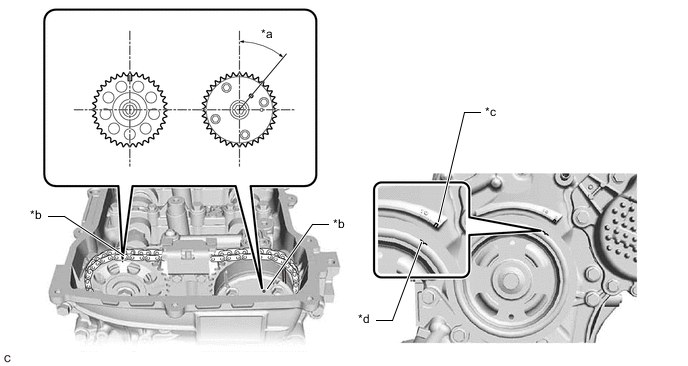
*a 39.5° *b Timing Mark *c "0" Timing Mark *d Groove -
Turn the crankshaft pulley and align its groove with the "0" timing mark of the timing chain or belt cover sub-assembly.
-
Check that the timing marks of the camshaft timing gear assembly and camshaft timing sprocket are at the positions shown in the illustration.
Tech Tips
If the timing marks are not as shown, turn the crankshaft one revolution clockwise.
OK Timing marks on camshaft timing gear assembly and camshaft timing sprocket are at the positions shown in the illustration. Tech Tips
If the result is not as specified, check for mechanical malfunctions that may have affected the valve timing, such as a jumped tooth or stretching of the timing chain.
Result Proceed to OK NG
NG
CHECK ENGINE MECHANICAL SYSTEM Click here
OK
-
-
INSPECT CAMSHAFT TIMING GEAR ASSEMBLY
-
Inspect the camshaft timing gear assembly.
Tech Tips
Result Proceed to OK NG
NG
REPLACE CAMSHAFT TIMING GEAR ASSEMBLY Click here
OK
-
-
INSPECT OIL CONTROL VALVE FILTER
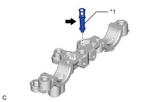
*1 Oil Control Valve Filter
-
Remove the oil control valve filter.
Tech Tips
-
Check that the filter is not clogged.
OK Filter is not clogged. Result Proceed to OK NG
OK
GO TO STEP 29 Click here
NG
-
-
REPLACE OIL CONTROL VALVE FILTER
-
Replace the oil control valve filter.
Tech Tips
Result Proceed to NEXT
NEXT
GO TO STEP 29 Click here
-
-
REPLACE CAMSHAFT TIMING GEAR ASSEMBLY
-
Replace the camshaft timing gear assembly.
Tech Tips
-
Perform "Inspection After Repair" after replacing the camshaft timing gear assembly.
Result Proceed to NEXT
NEXT
GO TO STEP 29 Click here
-
-
CHECK ENGINE MECHANICAL SYSTEM
-
Check for mechanical malfunctions that affect the valve timing, such as a jumped tooth or stretching of the timing chain.
Result Proceed to OK NG
OK
GO TO STEP 29 Click here
NG
-
-
REPAIR OR REPLACE MALFUNCTIONING PARTS, COMPONENT AND AREA
Tech Tips
Perform "Inspection After Repair" after repairing or replacing the engine mechanical system.
Result Proceed to NEXT
NEXT
GO TO STEP 29 Click here
-
REPLACE CAMSHAFT TIMING OIL CONTROL VALVE ASSEMBLY
-
Replace the camshaft timing oil control valve assembly.
Tech Tips
Result Proceed to NEXT
NEXT
GO TO STEP 29 Click here
-
-
REPLACE EGR VALVE ASSEMBLY
-
Replace the EGR valve assembly.
Tech Tips
-
Perform "Inspection After Repair" after replacing the EGR valve assembly.
Result Proceed to NEXT
NEXT
GO TO STEP 29 Click here
-
-
REPLACE AIR CLEANER FILTER ELEMENT SUB-ASSEMBLY
-
Replace the air cleaner filter element sub-assembly.
Result Proceed to NEXT
NEXT
GO TO STEP 29 Click here
-
-
REPAIR OR REPLACE INTAKE SYSTEM
-
Repair or replace the intake system.
Tech Tips
Perform "Inspection After Repair" after repairing or replacing the intake system.
Result Proceed to NEXT
NEXT
GO TO STEP 29 Click here
-
-
REPAIR OR REPLACE PCV HOSE
-
Repair or replace the PCV valve or hose.
Result Proceed to NEXT
NEXT
-
-
CLEAR DTC
-
Connect the GTS to the DLC3.
-
Turn the power switch on (IG).
-
Turn the GTS on.
-
Clear the DTCs.
Powertrain > Engine > Clear DTCs -
Turn the power switch off and wait for at least 30 seconds.
Result Proceed to NEXT
NEXT
-
-
CHECK WHETHER DTC OUTPUT RECURS (DTC P050B00)
Note
In this operation, the engine must be cold (approximately the same as the engine coolant temperature recorded in the freeze frame data).
-
Connect the GTS to the DLC3.
-
Turn the power switch on (IG).
-
Turn the GTS on.
-
Enter the following menus: Powertrain / Engine / Data List / Coolant Temperature.
Powertrain > Engine > Data ListTester Display Coolant Temperature -
Check that the engine coolant temperature is between -10 and 50°C (14 and 122°F).
-
Put the engine in Inspection Mode (Maintenance Mode).
Tech Tips
-
Start the engine and warm it up until the engine coolant temperature is the same as the engine coolant temperature in the freeze frame data.
-
Drive the vehicle in accordance with the driving pattern described in Confirmation Driving Pattern.
-
Enter the following menus: Powertrain / Engine / Utility / All Readiness.
Powertrain > Engine > UtilityTester Display All Readiness -
Input the DTC: P050B00.
-
Check the DTC judgment result.
Result Result Proceed to NORMAL
(DTCs are not output)
A ABNORMAL
(DTC P050B00 is output)
B
A
END
B
-
-
CHECK HARNESS AND CONNECTOR (MASS AIR FLOW METER SUB-ASSEMBLY CONNECTOR CONNECTION)
-
Check the connection and terminal contact pressure of connectors and wire harnesses between the mass air flow meter sub-assembly and ECM.
Result Proceed to NEXT
NEXT
-
-
CLEAR DTC
-
Connect the GTS to the DLC3.
-
Turn the power switch on (IG).
-
Turn the GTS on.
-
Clear the DTCs.
Powertrain > Engine > Clear DTCs -
Turn the power switch off and wait for at least 30 seconds.
Result Proceed to NEXT
NEXT
-
-
CHECK WHETHER DTC OUTPUT RECURS (DTC P050B00)
Note
In this operation, the engine must be cold (approximately the same as the engine coolant temperature recorded in the freeze frame data).
-
Connect the GTS to the DLC3.
-
Turn the power switch on (IG).
-
Turn the GTS on.
-
Enter the following menus: Powertrain / Engine / Data List / Coolant Temperature.
Powertrain > Engine > Data ListTester Display Coolant Temperature -
Check that the engine coolant temperature is between -10 and 50°C (14 and 122°F).
-
Put the engine in Inspection Mode (Maintenance Mode).
Tech Tips
-
Start the engine and warm it up until the engine coolant temperature is the same as the engine coolant temperature in the freeze frame data.
-
Drive the vehicle in accordance with the driving pattern described in Confirmation Driving Pattern.
-
Enter the following menus: Powertrain / Engine / Utility / All Readiness.
Powertrain > Engine > UtilityTester Display All Readiness -
Input the DTC: P050B00.
-
Check the DTC judgment result.
Result Result Proceed to NORMAL
(DTCs are not output)
A ABNORMAL
(DTC P050B00 is output)
B
A
END
B
-
-
CHECK HARNESS AND CONNECTOR (MASS AIR FLOW METER SUB-ASSEMBLY - ECM)
-
Disconnect the mass air flow meter sub-assembly connector.
-
Disconnect the ECM connector.
-
Measure the resistance according to the value(s) in the table below.
Standard Resistance Tester Connection Condition Specified Condition C5-3 (VG) - C31-137 (VG) Always Below 1 Ω C5-2 (E2G) - C31-104 (E2G) Always Below 1 Ω C5-3 (VG) or C31-137 (VG) - Body ground and other terminals Always 10 kΩ or higher Result Proceed to OK NG
NG
REPAIR OR REPLACE HARNESS OR CONNECTOR
OK
-
-
REPLACE MASS AIR FLOW METER SUB-ASSEMBLY
-
Replace the mass air flow meter sub-assembly.
Tech Tips
-
If the result of the inspection performed in step 13 (READ VALUE USING GTS (MASS AIR FLOW SENSOR)) indicated no problem, proceed to the next step without replacing the mass air flow meter sub-assembly.
-
Perform "Inspection After Repair" after replacing the mass air flow meter sub-assembly.
Result Proceed to NEXT
NEXT
-
-
CLEAR DTC
-
Connect the GTS to the DLC3.
-
Turn the power switch on (IG).
-
Turn the GTS on.
-
Clear the DTCs.
Powertrain > Engine > Clear DTCs -
Turn the power switch off and wait for at least 30 seconds.
Result Proceed to NEXT
NEXT
-
-
CHECK WHETHER DTC OUTPUT RECURS (DTC P050B00)
Note
In this operation, the engine must be cold (approximately the same as the engine coolant temperature recorded in the freeze frame data).
-
Connect the GTS to the DLC3.
-
Turn the power switch on (IG).
-
Turn the GTS on.
-
Enter the following menus: Powertrain / Engine / Data List / Coolant Temperature.
Powertrain > Engine > Data ListTester Display Coolant Temperature -
Check that the engine coolant temperature is between -10 and 50°C (14 and 122°F).
-
Put the engine in Inspection Mode (Maintenance Mode).
Tech Tips
-
Start the engine and warm it up until the engine coolant temperature is the same as the engine coolant temperature in the freeze frame data.
-
Drive the vehicle in accordance with the driving pattern described in Confirmation Driving Pattern.
-
Enter the following menus: Powertrain / Engine / Utility / All Readiness.
Powertrain > Engine > UtilityTester Display All Readiness -
Input the DTC: P050B00.
-
Check the DTC judgment result.
Result Result Proceed to NORMAL
(DTCs are not output)
A ABNORMAL
(DTC P050B00 is output)
B
A
END
B
REPLACE ECM Click here
-