RADIATOR REMOVAL
CAUTION / NOTICE / HINT
The necessary procedures (adjustment, calibration, initialization, or registration) that must be performed after parts are removed and installed, or replaced during radiator assembly removal/installation are shown below.
| Replaced Part or Performed Procedure | Necessary Procedure | Effect/Inoperative Function when Necessary Procedure not Performed | Link |
|---|---|---|---|
| Front bumper assembly |
|
|
|
| Change grille shutter control modes and/or perform initialization (w/ Exhaust Heat Recirculation System) | Grille Shutter system |
PROCEDURE
-
REMOVE HEADLIGHT ASSEMBLY LH
-
REMOVE HEADLIGHT ASSEMBLY RH
Tech Tips
Use the same procedure as for the LH side.
-
REMOVE NO. 1 ENGINE UNDER COVER
-
DRAIN ENGINE COOLANT (for Engine)
-
REMOVE INVERTER WATER PUMP ASSEMBLY
-
REMOVE HOOD LOCK ASSEMBLY
-
REMOVE INLET NO. 2 AIR CLEANER
-
REMOVE UPPER RADIATOR SUPPORT SUB-ASSEMBLY
-
w/o Vehicle Approaching Speaker Assembly:
-
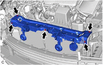
Disconnect the 2 horn connectors.
-
-
w/ Vehicle Approaching Speaker Assembly:
-
Disconnect the 2 horn connectors and vehicle approaching speaker assembly connector.
-
-
w/o Engine Hood Courtesy Switch:
-
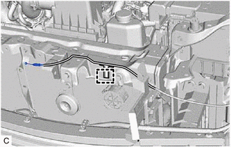
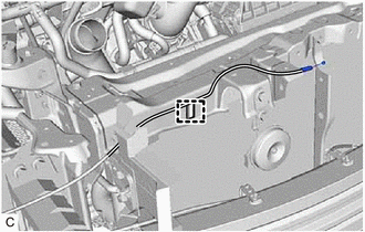
Disengage the 7 clamps to disconnect the wire harness from the upper radiator support sub-assembly and fan shroud assembly.
-
Disconnect the cooling fan motor RH connector and cooling fan motor LH connector.
-
-
w/ Engine Hood Courtesy Switch:
-
Disengage the 9 clamps to disconnect the wire harness from the upper radiator support sub-assembly and fan shroud assembly.
-
Disconnect the cooling fan motor RH connector and cooling fan motor LH connector.
-
-
for LHD:
-
Disengage the clamp to disconnect the hood lock control cable assembly from the upper radiator support sub-assembly.
-
-
for RHD:
-
Disengage the clamp to disconnect the hood lock control cable assembly from the upper radiator support sub-assembly.
-
-
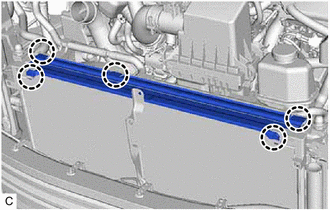
Remove the 5 bolts and upper radiator support sub-assembly.
-
-
REMOVE NO. 2 RADIATOR AIR GUIDE
-
Disengage the 5 claws to remove the No. 2 radiator air guide from the radiator assembly.
-
-
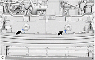
REMOVE FRONT ENERGY ABSORBER MOUNTING REINFORCEMENT LH (w/o Exhaust Heat Recirculation System)
for Type B:
-
REMOVE FRONT ENERGY ABSORBER MOUNTING REINFORCEMENT RH (w/o Exhaust Heat Recirculation System)
for Type B:
-
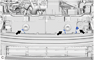
REMOVE FRONT BUMPER ENERGY ABSORBER (w/o Exhaust Heat Recirculation System)
for Type A:
for Type B:
-
REMOVE FRONT BUMPER REINFORCEMENT SUB-ASSEMBLY (w/o Exhaust Heat Recirculation System)
for Type A:
for Type B:
-
REMOVE NO. 1 RADIATOR AIR GUIDE LH (w/o Exhaust Heat Recirculation System)
-
REMOVE NO. 1 RADIATOR AIR GUIDE LH (w/ Exhaust Heat Recirculation System)
-
REMOVE NO. 1 RADIATOR AIR GUIDE RH (w/o Exhaust Heat Recirculation System)
-
REMOVE NO. 1 RADIATOR AIR GUIDE RH (w/ Exhaust Heat Recirculation System)
-
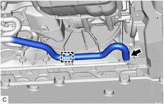
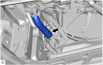
DISCONNECT NO. 1 WATER BY-PASS HOSE
-
Slide the clip and disconnect the No. 1 water by-pass hose.
-
-
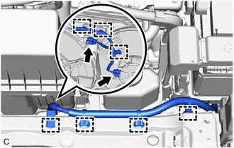
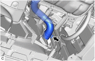
DISCONNECT NO. 2 WATER BY-PASS HOSE
-
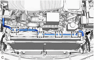
Disengage the 4 clamps.
-
Slide the clip and disconnect the No. 2 water by-pass hose.
-
-
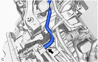
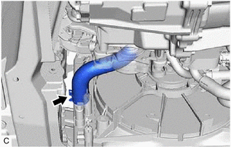
DISCONNECT INLET HYBRID RADIATOR HOSE
-
Disengage the clamp to disconnect the inlet hybrid radiator hose from the fan shroud assembly.
-
Slide the clip and disconnect the inlet hybrid radiator hose.
-
-
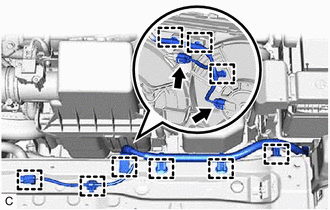
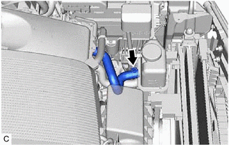
DISCONNECT INLET NO. 1 INVERTER COOLING HOSE
-
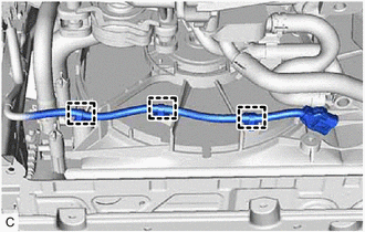
Disengage the 3 clamps to disconnect the wire harness from the fan shroud assembly.
-
Slide the clip and disconnect the inlet No. 1 inverter cooling hose.
-
-
DISCONNECT NO. 2 RADIATOR HOSE
-
Slide the clip and disconnect the No. 2 radiator hose.
-
-
DISCONNECT NO. 1 RADIATOR HOSE
-
Slide the clip and disconnect the No. 1 radiator hose.
-
-
DISCONNECT OUTLET NO. 1 INVERTER COOLING HOSE
-
Slide the clip and disconnect the outlet No. 1 inverter cooling hose.
-
-
REMOVE INVERTER RESERVE TANK ASSEMBLY
-
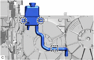
Disengage the clamp to disconnect the inlet hybrid water pump hose from the fan shroud assembly.
-
Disengage the 2 claws to remove the inverter reserve tank assembly from the fan shroud assembly.
-
-
REMOVE RADIATOR ASSEMBLY
-
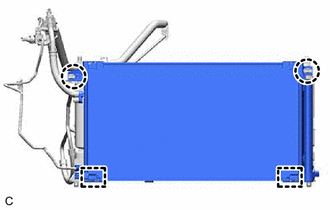
Disengage the 2 claws.
-
Disengage the 2 guides to separate the cooler condenser assembly from the radiator assembly.
Note
Make sure not to damage the cooler condenser assembly when removing the radiator assembly.
-
Remove the radiator assembly with the fan shroud assembly from the vehicle body.
Note
Do not apply excessive force to the cooler condenser assembly or pipe when removing the radiator assembly with the fan shroud assembly.
-
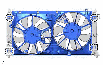
Disengage the 2 claws.
-
Disengage the 2 guides to remove the fan shroud assembly from the radiator assembly.
Note
Do not damage the radiator assembly when removing the fan shroud assembly.
-
-
REMOVE RADIATOR SUPPORT CUSHION
-
Remove the 2 radiator support cushions from the radiator assembly.
-
-
REMOVE RADIATOR SUPPORT GROMMET
-
Remove the 2 radiator support grommets from the radiator assembly.
-