TELEMATICS TRANSCEIVER REMOVAL
PROCEDURE
-
REMOVE DECK BOARD ASSEMBLY
-
REMOVE NO. 3 DECK BOARD SUB-ASSEMBLY
-
REMOVE REAR DECK FLOOR BOX (w/ Spare Tire)
-
REMOVE DECK FLOOR BOX LH (w/ Spare Tire)
-
PRECAUTION
Note
After turning the power switch off, waiting time may be required before disconnecting the cable from the negative (-) auxiliary battery terminal. Therefore, make sure to read the disconnecting the cable from the negative (-) auxiliary battery terminal notice before proceeding with work.
-
DISCONNECT CABLE FROM NEGATIVE AUXILIARY BATTERY TERMINAL
CAUTION:
Wait at least 90 seconds after disconnecting the cable from the negative (-) auxiliary battery terminal to disable the SRS system.
Note
When disconnecting the cable, some systems need to be initialized after the cable is reconnected.
-
REMOVE INSTRUMENT PANEL FINISH PLATE
-
REMOVE MULTI-DISPLAY ASSEMBLY WITH BRACKET
-
REMOVE DOOR SCUFF PLATE ASSEMBLY RH (for RHD)
-
REMOVE COWL SIDE TRIM BOARD RH (for RHD)
-
REMOVE CONSOLE ARMREST ASSEMBLY
-
REMOVE UPPER REAR CONSOLE PANEL
-
REMOVE UPPER NO. 1 CONSOLE PANEL GARNISH
-
REMOVE UPPER NO. 2 CONSOLE PANEL GARNISH
-
REMOVE INSTRUMENT SIDE PANEL RH
-
REMOVE INSTRUMENT SIDE PANEL LH
-
REMOVE NO. 1 INSTRUMENT PANEL SAFETY PAD SUB-ASSEMBLY
-
REMOVE NO. 1 INSTRUMENT PANEL UNDER COVER SUB-ASSEMBLY
-
REMOVE LOWER NO. 1 INSTRUMENT PANEL FINISH PANEL
-
REMOVE NO. 1 SWITCH HOLE BASE
-
REMOVE NO. 2 INSTRUMENT PANEL SAFETY PAD SUB-ASSEMBLY
-
REMOVE CENTER INSTRUMENT CLUSTER FINISH PANEL ASSEMBLY
-
REMOVE SHIFT LEVER KNOB SUB-ASSEMBLY
-
REMOVE UPPER REAR CONSOLE PANEL SUB-ASSEMBLY
-
REMOVE AIR CONDITIONING CONTROL ASSEMBLY
-
REMOVE RADIO RECEIVER ASSEMBLY WITH BRACKET
-
REMOVE TELEMATICS TRANSCEIVER WITH BRACKET
-
w/ Telematics Transceiver except G-BOOK
-
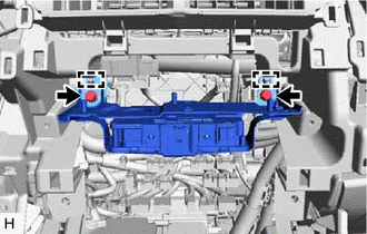
Remove the 2 bolts.
-
Detach the 2 guides and remove the telematics transceiver with bracket.
-
Disconnect each connector.
-
-
w/ Telematics Transceiver for G-BOOK
-
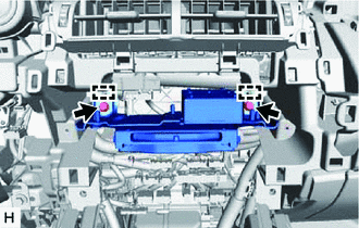
Remove the 2 bolts.
-
Detach the 2 guides and remove the telematics transceiver with bracket.
-
Disconnect each connector.
-
-
-
REMOVE TELEMATICS TRANSCEIVER
-
w/ Telematics Transceiver except G-BOOK
-
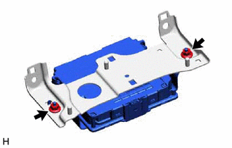
Remove the 2 nuts and telematics transceiver assembly.
-
-
w/ Telematics Transceiver for G-BOOK
-
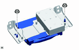
Remove the 2 nuts and telematics transceiver assembly.
-
-
-
REMOVE MAYDAY BATTERY (w/ Telematics Transceiver except G-BOOK)
-
REMOVE NO. 1 TELEPHONE BRACKET (w/ Telematics Transceiver for G-BOOK)
-
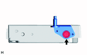
Remove the bolt and No. 1 telephone bracket.
-
-
REMOVE NO. 2 TELEPHONE BRACKET (w/ Telematics Transceiver for G-BOOK)
-
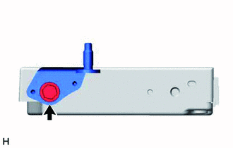
Remove the bolt and No. 2 telephone bracket.
-