TELEMATICS SYSTEM(w/ Telematics Transceiver for G-BOOK), Diagnostic DTC:B15DE
| DTC Code | DTC Name |
|---|---|
| B15DE | Telematics Transceiver Location Data Blackout |
DESCRIPTION
The telematics transceiver checks the reception condition of the location data every minute after the power switch is turned on (ACC). If the location data is not received from the radio receiver assembly for 5 minutes, this DTC will be stored.
| DTC No. | Detection Item | DTC Detection Condition | Trouble Area |
|---|---|---|---|
| B15DE | Telematics Transceiver Location Data Blackout | Location information from USB communication is interrupted |
|
WIRING DIAGRAM
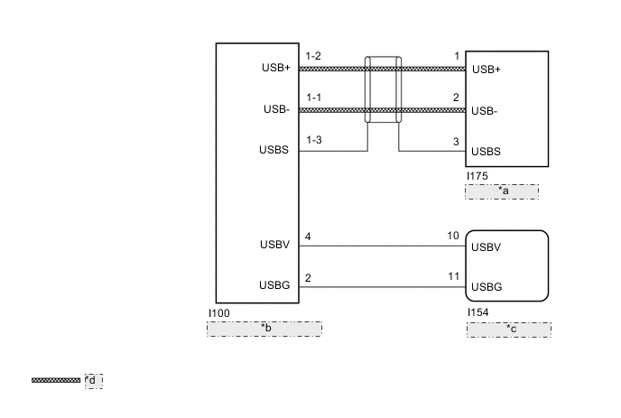
| *a | Navigation ECU |
| *b | Telematics Transceiver |
| *c | Radio Receiver Assembly |
| *d | USB Communication Line |
CAUTION / NOTICE / HINT
Note
-
Depending on the parts that are replaced during vehicle inspection or maintenance, performing initialization, registration or calibration may be needed. Refer to Precaution for G-BOOK.
-
When replacing the telematics transceiver, make sure to replace it with a new one.
-
When replacing the radio receiver assembly or navigation ECU, always replace it with a new one.
If a radio receiver assembly or navigation ECU which was installed to another vehicle is used, the following may occur:
-
A communication malfunction DTC may be stored.
-
The radio receiver assembly or navigation ECU may not operate normally.
PROCEDURE
-
CHECK DTC OUTPUT
-
Clear the DTCs.
Body Electrical > Navigation System > Clear DTCs -
Recheck for DTCs and check if the same DTC is output again.
Body Electrical > Navigation System > Trouble CodesResult Result Proceed to No DTCs are output. A B15DB and B15DE are output. B Only B15DE is output. C
A 
USE SIMULATION METHOD TO CHECK Click here
B
GO TO DTC B15DB Click here
C 
-
-
CHECK HARNESS AND CONNECTOR (RADIO RECEIVER ASSEMBLY - DCM [TELEMATICS TRANSCEIVER])
-
Disconnect the I154 radio receiver assembly connector.
-
Disconnect the I100 telematics transceiver connector.
-
Measure the resistance according to the value(s) in the table below.
Standard Resistance Tester Connection Condition Specified Condition I154-10 (USBV) - I100-4 (USBV) Always Below 1 Ω I154-11 (USBG) - I100-2 (USBG) Always Below 1 Ω I154-10 (USBV) - Body ground Always 10 kΩ or higher I154-11 (USBG) - Body ground Always 10 kΩ or higher Result Proceed to OK NG
NG
REPAIR OR REPLACE HARNESS OR CONNECTOR
OK
-
-
CHECK RADIO RECEIVER ASSEMBLY (USBV, USBG)
-
Disconnect the DCM (telematics transceiver) connector.
-
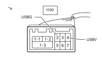
*a Front view of wire harness connector
(to Telematics Transceiver)
Measure the resistance according to the value(s) in the table below.
Standard Resistance Tester Connection Condition Specified Condition I100-2 (USBG) - Body ground Always Below 1 Ω -
Measure the voltage according to the value(s) in the table below.
Standard Voltage Tester Connection Switch Condition Specified Condition I100-4 (USBV) - I100-2 (USBG) Power switch on (ACC) 4.75 to 5.25 V Result Proceed to OK NG
NG
REPLACE RADIO RECEIVER ASSEMBLY Click here
OK
-
-
CHECK HARNESS AND CONNECTOR (TELEMATICS TRANSCEIVER - NAVIGATION ECU)
-
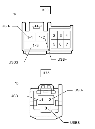
*a Front view of wire harness connector
(to Telematics Transceiver)
*b Front view of wire harness connector
(to Navigation ECU)
Disconnect the I100 telematics transceiver connector.
-
Disconnect the I175 navigation ECU connector.
-
Measure the resistance according to the value(s) in the table below.
Standard Resistance Tester Connection Condition Specified Condition I100-1-1 (USB-) - I175-2 (USB-) Always Below 1 Ω I100-1-2 (USB+) - I175-1 (USB+) Always Below 1 Ω I100-1-3 (USBS) - I175-3 (USBS) Always Below 1 Ω I100-1-1 (USB-) - Body ground Always 10 kΩ or higher I100-1-2 (USB+) - Body ground Always 10 kΩ or higher I100-1-3 (USBS) - Body ground Always 10 kΩ or higher Result Proceed to OK NG
NG
REPAIR OR REPLACE HARNESS OR CONNECTOR
OK
-
-
CHECK TELEMATICS TRANSCEIVER
-
Replace the telematics transceiver with a new one.
-
Clear the DTCs.
Body Electrical > Navigation System > Clear DTCs -
Recheck for DTCs and check that no DTCs are output.
Body Electrical > Navigation System > Trouble CodesOK No DTCs are output. Result Proceed to OK NG
OK
END (TELEMATICS TRANSCEIVER IS DEFECTIVE)
NG
-
-
CHECK NAVIGATION ECU
-
Replace the navigation ECU with a new one.
-
Clear the DTCs.
Body Electrical > Navigation System > Clear DTCs -
Recheck for DTCs and check that no DTCs are output.
Body Electrical > Navigation System > Trouble CodesOK No DTCs are output. Result Proceed to OK NG
OK
END (NAVIGATION ECU IS DEFECTIVE)
NG
REPLACE RADIO RECEIVER ASSEMBLY Click here
-