NAVIGATION SYSTEM Radio Broadcast cannot be Received or Poor Reception
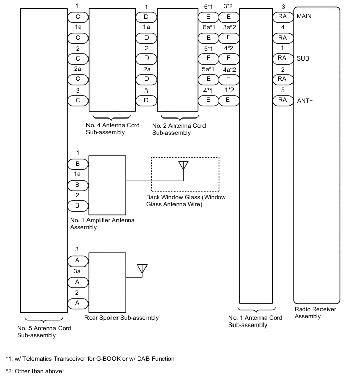
WIRING DIAGRAM
CAUTION / NOTICE / HINT
Note
When replacing the radio receiver assembly, always replace it with a new one.
If a radio receiver assembly which was installed to another vehicle is used, the following may occur:
-
A communication malfunction DTC may be stored.
-
The radio receiver assembly may not operate normally.
Tech Tips
Depending on the parts that are replaced during vehicle inspection or maintenance, performing initialization, registration or calibration may be needed. Refer to Precaution for Navigation System.
PROCEDURE
-
CHECK RADIO RECEIVER ASSEMBLY
-
Check the radio automatic station search function by activating it.
OK Automatic station search function stops on a station. Result Proceed to OK NG
OK 
USE SIMULATION METHOD TO CHECK Click here
NG 
-
-
CHECK OPTIONAL COMPONENTS
-
Check if any optional components that may decrease reception capacity, such as sunshade film or a telephone antenna, are installed.
OK Optional components are not installed. Note
Do not remove optional components without the permission of the customer.
Result Proceed to OK NG
NG
REMOVE OPTIONAL COMPONENTS AND CHECK AGAIN (SEE NOTICE ABOVE)
OK
-
-
CHECK RADIO RECEIVER ASSEMBLY
-
Preparation for check
-
Disconnect the RA radio receiver assembly connector.
-
-
Check for noise
-
Turn the power switch on (ACC) with the radio receiver assembly connector connected.
-
Turn the radio receiver assembly on and enter AM mode.
-
Place a screwdriver, thin wire or other metal object on the radio receiver assembly antenna jack and check that noise can be heard from the speakers.
OK Noise can be heard from the speakers.
Result Proceed to OK NG -
NG
REPLACE RADIO RECEIVER ASSEMBLY Click here
OK
-
-
CHECK BACK WINDOW GLASS (WINDOW GLASS ANTENNA WIRE)
-
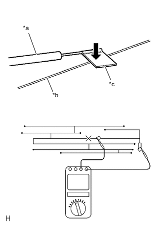
*a Tester Probe *b Antenna Wire *c Tin Foil Check for continuity in the window glass antenna wire.
Tech Tips
Check for continuity at the center of each antenna wire as shown in the illustration.
Note
When cleaning the glass, wipe it in the direction of the wire with a soft dry cloth. Take care not to damage the wire. Do not use detergents or glass cleaners with abrasive ingredients. When measuring resistance, wrap a piece of tin foil around the tip of each probe and press the foil against the wire with your finger as shown in the illustration.
OK There is continuity in the window glass antenna wire. Result Proceed to OK NG
NG
REPAIR BACK WINDOW GLASS (WINDOW GLASS ANTENNA WIRE)
OK
-
-
INSPECT RADIO RECEIVER ASSEMBLY
-
Disconnect the RA radio receiver assembly connector.
-
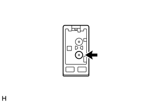
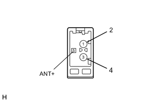
Measure the voltage according to the value(s) in the table below.
Standard Voltage Tester Connection Switch Condition Specified Condition 5 (ANT+) - Body ground Power switch on (ACC), radio switch on and FM or AM selected 11 to 14 V Result Proceed to OK NG
NG
REPLACE RADIO RECEIVER ASSEMBLY Click here
OK
-
-
CHECK VEHICLE TYPE
-
Check the vehicle type.
Result Result Proceed to w/ Telematics Transceiver for G-BOOK or w/ DAB Function A Other than above B
B 
CHECK NO. 1 ANTENNA CORD SUB-ASSEMBLY Click here
A
-
-
CHECK NO. 1 ANTENNA CORD SUB-ASSEMBLY
-
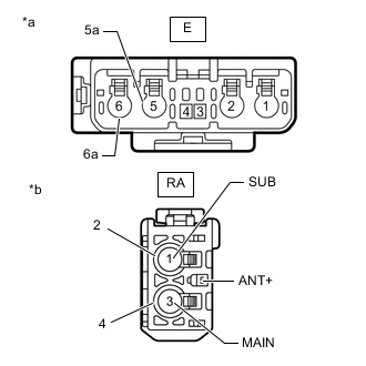
*a Front view of wire harness connector
(to No. 2 Antenna Cord Sub-assembly)
*b Front view of wire harness connector
(to Radio Receiver Assembly)
Disconnect the antenna connector from the No. 2 antenna cord sub-assembly.
-
Disconnect the antenna connector from the radio receiver assembly.
-
Measure the resistance according to the value(s) in the table below.
Standard Resistance Tester Connection Condition Specified Condition E-6 - RA-3 (MAIN) Always Below 1 Ω E-6a - RA-4 Always Below 1 Ω E-5 - RA-1 (SUB) Always Below 1 Ω E-5a - RA-2 Always Below 1 Ω E-4 - RA-5 (ANT+) Always Below 1 Ω E-6 - Body ground Always 10 kΩ or higher E-6a - Body ground Always 10 kΩ or higher E-5 - Body ground Always 10 kΩ or higher E-5a - Body ground Always 10 kΩ or higher E-4 - Body ground Always 10 kΩ or higher Result Proceed to OK NG
NG
REPLACE NO. 1 ANTENNA CORD SUB-ASSEMBLY Click here
OK
-
-
CHECK NO. 2 ANTENNA CORD SUB-ASSEMBLY
-
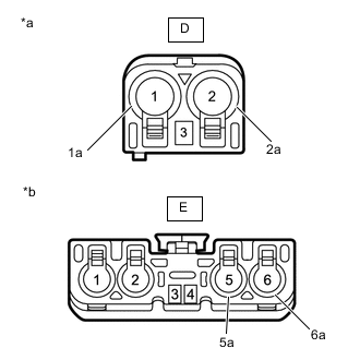
*a Front view of wire harness connector
(to No. 4 Antenna Cord Sub-assembly)
*b Front view of wire harness connector
(to No. 1 Antenna Cord Sub-assembly)
Disconnect the antenna connector from the No. 4 antenna cord sub-assembly.
-
Disconnect the antenna connector from the No. 1 antenna cord sub-assembly.
-
Measure the resistance according to the value(s) in the table below.
Standard Resistance Tester Connection Condition Specified Condition D-1 - E-6 Always Below 1 Ω D-1a - E-6a Always Below 1 Ω D-2 - E-5 Always Below 1 Ω D-2a - E-5a Always Below 1 Ω D-3 - E-4 Always Below 1 Ω D-1 - Body ground Always 10 kΩ or higher D-1a - Body ground Always 10 kΩ or higher D-2 - Body ground Always 10 kΩ or higher D-2a - Body ground Always 10 kΩ or higher D-3 - Body ground Always 10 kΩ or higher Result Proceed to OK NG
NG
REPLACE NO. 2 ANTENNA CORD SUB-ASSEMBLY Click here
OK
-
-
CHECK NO. 4 ANTENNA CORD SUB-ASSEMBLY
-
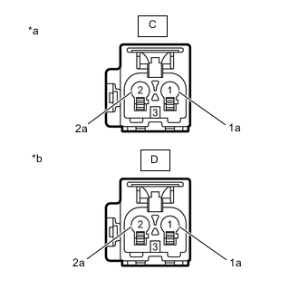
*a Front view of wire harness connector
(to No. 5 Antenna Cord Sub-assembly)
*b Front view of wire harness connector
(to No. 2 Antenna Cord Sub-assembly)
Disconnect the antenna connector from the No. 5 antenna cord sub-assembly.
-
Disconnect the antenna connector from the No. 2 antenna cord sub-assembly.
-
Measure the resistance according to the value(s) in the table below.
Standard Resistance Tester Connection Condition Specified Condition C-1 - D-1 Always Below 1 Ω C-1a - D-1a Always Below 1 Ω C-2 - D-2 Always Below 1 Ω C-2a - D-2a Always Below 1 Ω C-3 - D-3 Always Below 1 Ω C-1 - Body ground Always 10 kΩ or higher C-1a - Body ground Always 10 kΩ or higher C-2 - Body ground Always 10 kΩ or higher C-2a - Body ground Always 10 kΩ or higher C-3 - Body ground Always 10 kΩ or higher Result Proceed to OK NG
NG
REPLACE NO. 4 ANTENNA CORD SUB-ASSEMBLY Click here
OK
-
-
CHECK NO. 5 ANTENNA CORD SUB-ASSEMBLY
-
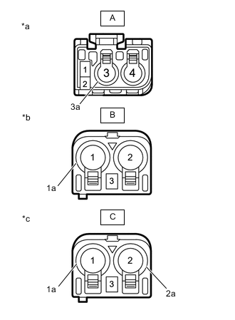
*a Front view of wire harness connector
(to Rear Spoiler Sub-assembly)
*b Front view of wire harness connector
(to No. 1 Amplifier Antenna Assembly)
*c Front view of wire harness connector
(to No. 4 Antenna Cord Sub-assembly)
Disconnect the antenna connector from the rear spoiler sub-assembly.
-
Disconnect the antenna connector from the No. 1 amplifier antenna assembly.
-
Disconnect the antenna connector from the No. 4 antenna cord sub-assembly.
-
Measure the resistance according to the value(s) in the table below.
Standard Resistance Tester Connection Condition Specified Condition A-3 - C-1 Always Below 1 Ω A-3a - C-1a Always Below 1 Ω A-2 - C-3 Always Below 1 Ω B-1 - C-2 Always Below 1 Ω B-1a - C-2a Always Below 1 Ω B-2 - C-3 Always Below 1 Ω A-3 - Body ground Always 10 kΩ or higher A-3a - Body ground Always 10 kΩ or higher A-2 - Body ground Always 10 kΩ or higher B-1 - Body ground Always 10 kΩ or higher B-1a - Body ground Always 10 kΩ or higher B-2 - Body ground Always 10 kΩ or higher Result Proceed to OK NG
NG
REPLACE NO. 5 ANTENNA CORD SUB-ASSEMBLY Click here
OK
-
-
CHECK NO. 1 AMPLIFIER ANTENNA ASSEMBLY
-
Replace the No. 1 amplifier antenna assembly with a new or known good one.
OK Radio broadcasts can be received normally. Result Proceed to OK NG
OK
END (NO. 1 AMPLIFIER ANTENNA ASSEMBLY IS DEFECTIVE)
NG
-
-
CHECK REAR SPOILER SUB-ASSEMBLY
-
Replace the rear spoiler sub-assembly with a new or known good one.
OK Radio broadcasts can be received normally. Result Proceed to OK NG
OK
END (REAR SPOILER SUB-ASSEMBLY IS DEFECTIVE)
NG
REPLACE RADIO RECEIVER ASSEMBLY Click here
-
-
CHECK NO. 1 ANTENNA CORD SUB-ASSEMBLY
-
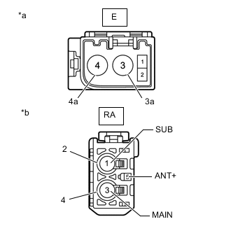
*a Front view of wire harness connector
(to No. 2 Antenna Cord Sub-assembly)
*b Front view of wire harness connector
(to Radio Receiver Assembly)
Disconnect the antenna connector from the No. 2 antenna cord sub-assembly.
-
Disconnect the antenna connector from the radio receiver assembly.
-
Measure the resistance according to the value(s) in the table below.
Standard Resistance Tester Connection Condition Specified Condition E-3 - RA-3 (MAIN) Always Below 1 Ω E-3a - RA-4 Always Below 1 Ω E-4 - RA-1 (SUB) Always Below 1 Ω E-4a - RA-2 Always Below 1 Ω E-1 - RA-5 (ANT+) Always Below 1 Ω E-3 - Body ground Always 10 kΩ or higher E-3a - Body ground Always 10 kΩ or higher E-4 - Body ground Always 10 kΩ or higher E-4a - Body ground Always 10 kΩ or higher E-1 - Body ground Always 10 kΩ or higher Result Proceed to OK NG
NG
REPLACE NO. 1 ANTENNA CORD SUB-ASSEMBLY Click here
OK
-
-
CHECK NO. 2 ANTENNA CORD SUB-ASSEMBLY
-
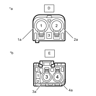
*a Front view of wire harness connector
(to No. 3 Antenna Cord Sub-assembly)
*b Front view of wire harness connector
(to No. 4 Antenna Cord Sub-assembly)
Disconnect the antenna connector from the No. 4 antenna cord sub-assembly.
-
Disconnect the antenna connector from the No. 1 antenna cord sub-assembly.
-
Measure the resistance according to the value(s) in the table below.
Standard Resistance Tester Connection Condition Specified Condition D-1 - E-3 Always Below 1 Ω D-1a - E-3a Always Below 1 Ω D-2 - E-4 Always Below 1 Ω D-2a - E-4a Always Below 1 Ω D-3 - E-1 Always Below 1 Ω D-1 - Body ground Always 10 kΩ or higher D-1a - Body ground Always 10 kΩ or higher D-2 - Body ground Always 10 kΩ or higher D-2a - Body ground Always 10 kΩ or higher D-3 - Body ground Always 10 kΩ or higher Result Proceed to OK NG
OK
GO TO STEP 9 Click here
NG
REPLACE NO. 2 ANTENNA CORD SUB-ASSEMBLY Click here
-