AUDIO AND VISUAL SYSTEM(for 8 Inch Display), Diagnostic DTC:B15D6
| DTC Code | DTC Name |
|---|---|
| B15D6 | Display Disconnected |
DESCRIPTION
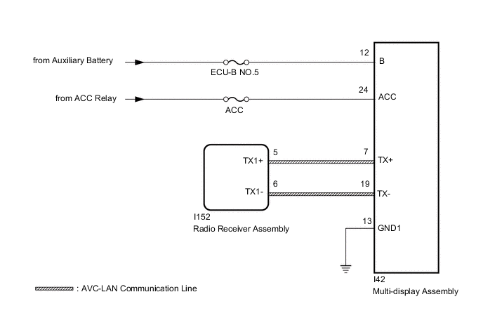
The multi-display assembly and radio receiver assembly are connected by the AVC-LAN communication line.
This DTC is stored when an AVC-LAN communication error occurs between the multi-display assembly and radio receiver assembly.
| DTC No. | Detection Item | DTC Detection Condition | Trouble Area |
|---|---|---|---|
| B15D6 | Display Disconnected | A device that is listed in the AVC-LAN connected device record of the master unit is missing |
|
Tech Tips
For the AVC-LAN communication line, the radio receiver assembly is the master unit.
WIRING DIAGRAM
CAUTION / NOTICE / HINT
Note
-
Inspect the fuses for circuits related to this system before performing the following procedure.
-
When replacing the radio receiver assembly, always replace it with a new one.
If a radio receiver assembly which was installed to another vehicle is used, the following may occur:
-
A communication malfunction DTC may be stored.
-
The radio receiver assembly may not operate normally.
Tech Tips
Depending on the parts that are replaced during vehicle inspection or maintenance, performing initialization, registration or calibration may be needed. Refer to Precaution for Audio and Visual System.
PROCEDURE
-
CHECK OPTIONAL COMPONENTS (INCLUDING ASSOCIATED WIRING)
-
Check for optional components.
-
Check that optional components (including associated wiring) which generate radio waves are not installed.
Result Result Proceed to Optional components (including associated wiring) are installed. A Optional components (including associated wiring) are not installed. B Tech Tips
-
Electrical noise from radio waves generated by optional components or the wiring for those components may affect AVC-LAN communication.
-
This DTC may be stored when an AVC-LAN communication error occurs due to electrical noise.
-
-
B 
GO TO STEP 4 Click here
A 
-
-
REMOVE OPTIONAL COMPONENTS (INCLUDING ASSOCIATED WIRING)
-
Remove optional components (including associated wiring).
Note
Do not remove optional components or associated wiring without the permission of the customer.
Result Proceed to NEXT
NEXT
-
-
CHECK DTC
-
Clear the DTCs.
Body Electrical > Navigation System > Clear DTCs -
Recheck for DTCs and check that no DTCs are output.
Body Electrical > Navigation System > Trouble CodesOK No DTCs are output. Result Proceed to OK NG
OK 
END (COMMUNICATION MALFUNCTION DUE TO NOISE)
NG
-
-
CHECK HARNESS AND CONNECTOR (MULTI-DISPLAY ASSEMBLY - BATTERY AND BODY GROUND)
-
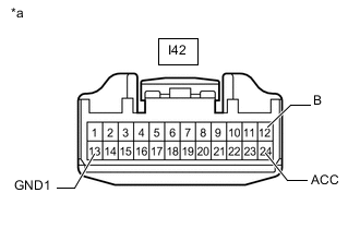
*a Front view of wire harness connector
(to Multi-display Assembly)
Disconnect the multi-display assembly connector.
-
Measure the resistance according to the value(s) in the table below.
Standard Resistance Tester Connection Condition Specified Condition I42-13 (GND1) - Body ground Always Below 1 Ω -
Measure the voltage according to the value(s) in the table below.
Standard Voltage Tester Connection Condition Specified Condition I42-12 (B) - Body ground Power switch off 11 to 14 V I42-24 (ACC) - Body ground Power switch on (ACC) 11 to 14 V Result Proceed to OK NG
NG
REPAIR OR REPLACE HARNESS OR CONNECTOR
OK
-
-
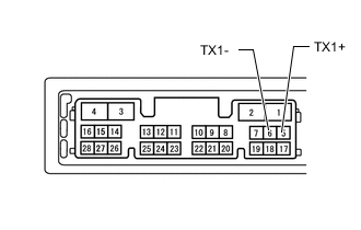
INSPECT RADIO RECEIVER ASSEMBLY (TX1+, TX1-)
-
Remove the radio receiver assembly.
-
Measure the resistance according to the value(s) in the table below.
Standard Resistance Tester Connection Condition Specified Condition 5 (TX1+) - 6 (TX1-) Always 60 to 80 Ω Result Proceed to OK NG
NG
REPLACE RADIO RECEIVER ASSEMBLY Click here
OK
-
-
CHECK HARNESS AND CONNECTOR (RADIO RECEIVER ASSEMBLY - MULTI-DISPLAY ASSEMBLY)
-
Disconnect the I152 radio receiver assembly connector.
-
Disconnect the I42 multi-display assembly connector.
-
Measure the resistance according to the value(s) in the table below.
Standard Resistance Tester Connection Condition Specified Condition I152-5 (TX1+) - I42-7 (TX+) Always Below 1 Ω I152-6 (TX1-) - I42-19 (TX-) Always Below 1 Ω I152-5 (TX1+) - Body ground Always 10 kΩ or higher I152-6 (TX1-) - Body ground Always 10 kΩ or higher Result Proceed to OK NG
NG
REPAIR OR REPLACE HARNESS OR CONNECTOR
OK
-
-
CHECK MULTI-DISPLAY ASSEMBLY
-
Replace the multi-display assembly with a new or known good one.
-
Clear the DTCs.
Body Electrical > Navigation System > Clear DTCs -
Recheck for DTCs and check that no DTCs are output.
Body Electrical > Navigation System > Trouble CodesOK No DTCs are output. Result Proceed to OK NG
OK
END (MULTI-DISPLAY ASSEMBLY IS DEFECTIVE)
NG
REPLACE RADIO RECEIVER ASSEMBLY Click here
-