АВТОМАТИЧЕСКАЯ ТРАНСМИССИЯ В СБОРЕ (если опорный мост двигателя используется) УСТАНОВКА

PROCEDURE
-
INSTALL TORQUE CONVERTER ASSEMBLY
-
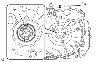
*a Matchmark *b Key Turn the front oil pump drive gear so that either key is at the top and place a matchmark on the transaxle housing to indicate the position of the key.
-
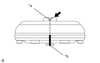
*a Groove *b Matchmark 
MP Grease Place a matchmark on the torque converter assembly so that the position of its groove is clearly indicated.
-
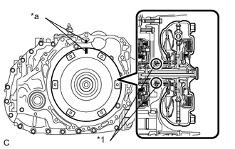
*1 Front Oil Pump Oil Seal *a Matchmark Align the matchmark on the torque converter assembly with the one on the transaxle housing and engage the splines of the input shaft with the turbine runner splines.
Note
-
Install the torque converter assembly to the input shaft while keeping it horizontal.
-
Do not damage the front oil pump oil seal.
-
-
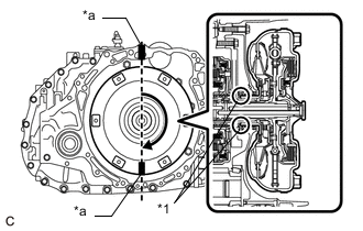
*1 Front Oil Pump Oil Seal *a Matchmark Rotate the torque converter assembly approximately 180° and engage the splines of the stator shaft with the stator assembly.
Note
-
Do not push the torque converter assembly excessively when rotating it.
-
Install the torque converter assembly to the input shaft while keeping it horizontal.
-
Do not damage the front oil pump oil seal.
-
-
*1 Front Oil Pump Oil Seal *a Matchmark Rotate the torque converter assembly approximately 180° again, align the matchmark on the torque converter assembly with the one on the transaxle housing and insert the keys of the front oil pump drive gear into the grooves of the torque converter assembly.
Note
-
Do not push the torque converter assembly excessively when rotating it.
-
Install the torque converter assembly to the input shaft while keeping it horizontal.
-
Do not damage the front oil pump oil seal.
-
-
Clean the drive plate and torque converter assembly setting bolt holes.
-
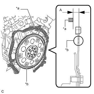
*a Engine Assembly Surface *b Drive Plate and Ring Gear Sub-assembly Surface Using a vernier caliper and straightedge, measure the dimension (A) between the automatic transaxle assembly contact surface of the engine assembly*a and the torque converter assembly contact surface of the drive plate and ring gear sub-assembly*b.
Note
Make sure to deduct the thickness of the straightedge.
-
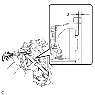
Using a vernier caliper and straightedge, measure the dimension (B) shown in the illustration and check that the dimension (B) is more than the dimension (A), which was measured in the previous step.
Standard Dimension (A) + 1 mm (0.0394 in.) or more Note
-
Make sure to deduct the thickness of the straightedge.
-
If the automatic transaxle assembly is installed to the engine assembly with the torque converter assembly not sufficiently inserted, the torque converter assembly may be damaged.
-
Do not include the thickness of the set block.
-
-
-
INSTALL BREATHER PLUG HOSE
-
Install the breather plug sub-assembly to the breather plug hose.
-
Install the breather plug hose to the No. 1 breather plug (ATM).
-
-
INSTALL TRANSMISSION CASE PLUG ASSEMBLY
-
Coat the O-ring of a new transmission case plug assembly with Toyota Genuine ATF WS.
-
Install the transmission case plug assembly to the automatic transaxle assembly.
-
-
INSTALL WIRE HARNESS CLAMP BRACKET
-
Install the wire harness clamp bracket to the automatic transaxle case sub-assembly with the bolt.
- Torque:
- 8.5 N*m { 87 kgf*cm, 75 in.*lbf }
-
-
INSTALL NO. 1 TRANSMISSION CONTROL CABLE BRACKET
-
Install the No. 1 transmission control cable bracket to the automatic transaxle case sub-assembly with the 2 bolts.
- Torque:
- 12 N*m { 122 kgf*cm, 9 ft.*lbf }
-
-
INSTALL FRONT ENGINE MOUNTING BRACKET
-
Install the front engine engine mounting bracket to the automatic transaxle assembly with the 4 bolts.
- Torque:
- 64 N*m { 653 kgf*cm, 47 ft.*lbf }
-
-
INSTALL ENGINE MOUNTING BRACKET LH
-
Install the engine mounting bracket LH to the automatic transaxle case sub-assembly with the 3 bolts.
- Torque:
- 64 N*m { 653 kgf*cm, 47 ft.*lbf }
-
-
INSTALL NO. 1 OIL COOLER TUBE SUB-ASSEMBLY WITHOUT HOSE
-
INSTALL TRANSMISSION OIL COOLER
-
CONNECT OUTLET NO. 3 OIL COOLER HOSE
-
CONNECT INLET NO. 2 OIL COOLER HOSE
-
SUPPORT ENGINE ASSEMBLY
-
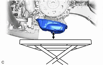
Set an engine lifter.
Note
Make sure that there is clearance between the engine oil pan assembly and engine lifter.
-
-
INSTALL AUTOMATIC TRANSAXLE ASSEMBLY
-
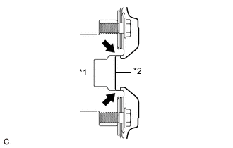
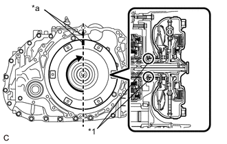
*1 Crankshaft *2 Torque Converter Assembly Centerpiece Clutch Spline Grease Apply clutch spline grease to the surface of the crankshaft that contacts the torque converter assembly centerpiece.
Clutch Spline Grease Toyota Genuine Clutch Spline Grease or equivalent Maximum Grease Amount Approximately 1 g (0.0353 oz) -
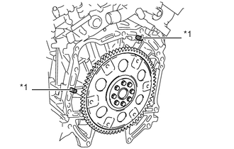
*1 Knock Pin Confirm that the 2 knock pins are installed on the engine assembly and are not damaged.
-
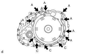
While keeping the engine assembly and automatic transaxle assembly horizontal, align the knock pins with the holes in the automatic transaxle assembly and install the automatic transaxle assembly with the 11 bolts shown in the illustration.
- Torque:
- Bolt (A)
- 64 N*m { 653 kgf*cm, 47 ft.*lbf }
- Bolt (B)
- 46 N*m { 469 kgf*cm, 34 ft.*lbf }
- Bolt (C)
- 43 N*m { 438 kgf*cm, 32 ft.*lbf }
Bolt Length Bolt Length (A) 55 mm (2.17 in.) (B) 41 mm (1.61 in.) (C) 33 mm (1.30 in.) Note
-
Confirm that the knock pins are installed to the automatic transaxle assembly contact surface of the cylinder block sub-assembly before installing the automatic transaxle assembly.
-
Do not forcibly pry on the automatic transaxle assembly.
-
Check that the torque converter assembly rotates.
-
-
INSTALL BELT
-
Install SST to the vehicle body as shown in the illustration.
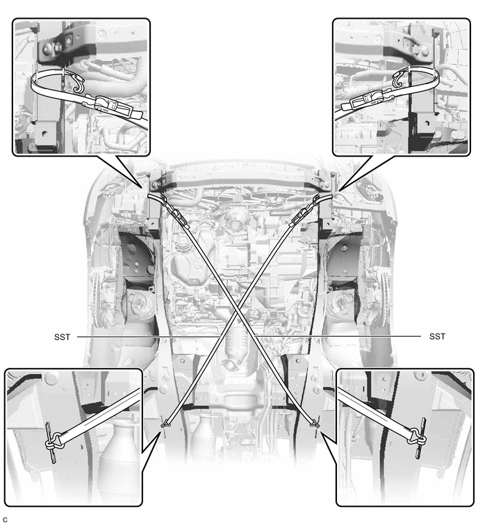
- SST
- 09727-00110
-
Using the ratchet buckle, tighten the 2 belts until there is no slack.
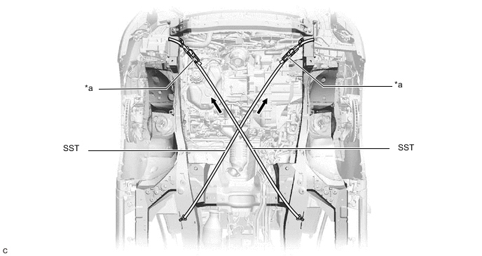
*a Ratchet Buckle - -
-
-
INSTALL ENGINE MOUNTING INSULATOR LH
-
Install the engine mounting insulator LH to the automatic transaxle assembly with the nut.
- Torque:
- 95 N*m { 969 kgf*cm, 70 ft.*lbf }
-
-
INSTALL FRONT ENGINE MOUNTING INSULATOR ASSEMBLY
-
Install the front engine mounting insulator assembly to the front engine mounting bracket with the bolt.
- Torque:
- 87 N*m { 887 kgf*cm, 64 ft.*lbf }
-
-
REMOVE ENGINE SUPPORT BAR
-
Remove the 2 bolts and SST (support bar) from the vehicle body.
-
Remove the nut, stud bolt and SST (support bar) from the engine mounting bracket RH.
-
-
INSTALL ENGINE MOUNTING INSULATOR RH
-
Install the engine mounting insulator RH to the engine mounting bracket RH with the nut.
- Torque:
- 95 N*m { 969 kgf*cm, 70 ft.*lbf }
-
-
INSTALL FRONT FRAME ASSEMBLY
-
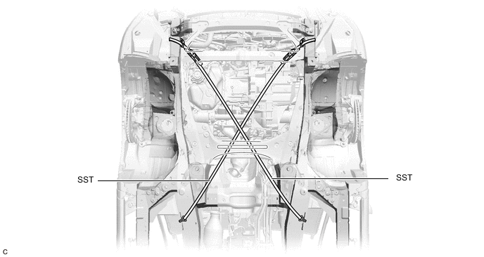
REMOVE BELT
-
Remove SST from the vehicle body.
-
Connect the windshield washer jar assembly to the vehicle body with the bolt and nut.
- Torque:
- 5.5 N*m { 56 kgf*cm, 49 in.*lbf }
-
-
INSTALL DRIVE PLATE AND TORQUE CONVERTER ASSEMBLY SETTING BOLT
-
Remove any remaining adhesive from the 6 drive plate and torque converter assembly setting bolts.
-
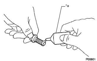
*a Adhesive Apply a few drops of adhesive to 2 or 3 threads at the tip of each of the 6 drive plate and torque converter assembly setting bolts.
Adhesive Toyota Genuine Adhesive 1324, Three Bond 1324 or equivalent Note
Make sure to install the 6 drive plate and torque converter assembly setting bolts immediately after applying adhesive to prevent foreign matter from attaching to them.
-
Turn the crankshaft to gain access to the installation locations of the 6 drive plate and torque converter assembly setting bolts and install each drive plate and torque converter assembly setting bolt while holding the crankshaft pulley bolt with a wrench.
- Torque:
- 41 N*m { 418 kgf*cm, 30 ft.*lbf }
Note
First install the black colored drive plate and torque converter assembly setting bolt, and then the remaining 5 silver colored drive plate and torque converter assembly setting bolts.
-
-
INSTALL FLYWHEEL HOUSING UNDER COVER
-
Install the flywheel housing under cover to the automatic transaxle case sub-assembly with the 2 bolts.
- Torque:
- 10 N*m { 102 kgf*cm, 7 ft.*lbf }
-
-
REMOVE ENGINE SUPPORT BRIDGE
-
Remove SST from the vehicle body.
Note
Prevent SST from contacting the vehicle body or windshield glass.
-
-
REMOVE ENGINE HANGER
-
Remove the 2 bolts and No. 2 engine hanger from the cylinder head LH.
-
Remove the bolt, SST (collar) and No. 1 engine hanger from engine hanger attachment.
-
Remove the 2 bolts and SST (engine hanger attachment) from cylinder head RH.
-
-
CONNECT FRONT ENGINE MOUNTING INSULATOR ASSEMBLY
-
CONNECT ENGINE MOUNTING INSULATOR LH
-
CONNECT ENGINE MOUNTING INSULATOR RH
-
CONNECT REAR ENGINE MOUNTING INSULATOR ASSEMBLY
-
CONNECT TRANSMISSION OIL THERMOSTAT
-
INSTALL FRONT DRIVE SHAFT HOLE SNAP RING (for LH Side)
-
INSTALL FRONT DRIVE SHAFT ASSEMBLY LH
-
INSTALL FRONT DRIVE SHAFT ASSEMBLY RH
-
CONNECT FRONT LOWER NO. 1 SUSPENSION ARM SUB-ASSEMBLY LH
-
CONNECT FRONT LOWER NO. 1 SUSPENSION ARM SUB-ASSEMBLY RH
Tech Tips
Use the same procedure as for the LH side.
-
CONNECT TIE ROD ASSEMBLY LH
-
CONNECT TIE ROD ASSEMBLY RH
Tech Tips
Use the same procedure as for the LH side.
-
INSTALL FRONT SPEED SENSOR
-
CONNECT STEERING INTERMEDIATE SHAFT ASSEMBLY
-
INSTALL FRONT AXLE SHAFT NUT
-
INSTALL FRONT STABILIZER LINK ASSEMBLY LH
-
INSTALL FRONT STABILIZER LINK ASSEMBLY RH
Tech Tips
Use the same procedure as for the LH side.
-
INSTALL EXHAUST MANIFOLD TO HEAD GASKET (for Bank 1)
-
INSTALL EXHAUST MANIFOLD (TWC: Front Catalyst)
-
INSTALL FRONT EXHAUST PIPE ASSEMBLY
-
INSTALL NO. 1 EXHAUST PIPE SUPPORT BRACKET (for Lower Side)
-
INSTALL FRONT NO. 3 EXHAUST PIPE SUB-ASSEMBLY
-
INSTALL WIRE HARNESS CLAMP BRACKET
-
Install the wire harness clamp bracket to the cylinder head RH with the bolt.
- Torque:
- 13 N*m { 133 kgf*cm, 10 ft.*lbf }
-
Engage the hose clamp and 3 wire harness clamps.
-
Connect the air fuel ratio sensor (for Bank 1) connector.
-
-
INSTALL BREATHER PLUG HOSE
-
Engage the 3 hose clamps to install the breather plug hose.
-
-
CONNECT ENGINE WIRE
-
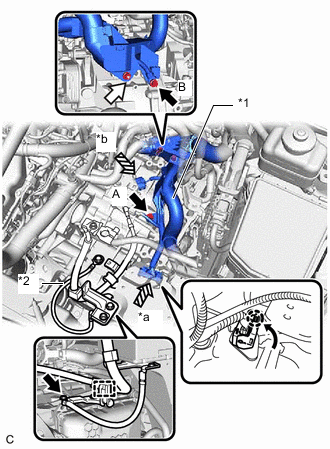
*a Transmission Wire Connector *b Park/Neutral Position Switch Assembly Connector *1 Engine Wire *2 Earth Wire Bolt 
Nut Engage the clamp to connect the engine wire.
-
Connect the earth wire with the bolt.
- Torque:
- 8.5 N*m { 87 kgf*cm, 75 in.*lbf }
-
Connect the engine wire to the automatic transaxle case sub-assembly with the 2 bolts and nut.
- Torque:
- Bolt (A)
- 25.5 N*m { 260 kgf*cm, 19 ft.*lbf }
- Bolt (B)
- 19.1 N*m { 195 kgf*cm, 14 ft.*lbf }
- Nut
- 8.5 N*m { 87 kgf*cm, 75 in.*lbf }
-
Connect the park/neutral position switch connector.
-
Connect the connector of the transmission wire connector and rotate the lever to engage the claw.
Tech Tips
Rotate the lever until the claw of the transmission wire connector makes a click sound.
-
-
INSTALL AIR SURGE TANK TO INTAKE MANIFOLD GASKET
-
INSTALL INTAKE AIR SURGE TANK ASSEMBLY
-
CONNECT PURGE VALVE (PURGE VSV)
-
INSTALL THROTTLE BODY WITH MOTOR ASSEMBLY
-
CONNECT VENTILATION HOSE
-
CONNECT NO. 1 TRANSMISSION OIL COOLER HOSE
-
CONNECT OUTLET NO. 1 OIL COOLER HOSE
-
INSTALL RADIATOR PIPE ASSEMBLY
-
Install the radiator pipe assembly to the automatic transaxle assembly with the bolt.
- Torque:
- 23 N*m { 235 kgf*cm, 17 ft.*lbf }
-
-
CONNECT NO. 3 WATER BY-PASS HOSE
-
CONNECT NO. 4 WATER BY-PASS HOSE
-
CONNECT TRANSMISSION CONTROL CABLE ASSEMBLY
-
INSTALL STARTER ASSEMBLY
-
INSTALL OUTER COWL TOP PANEL SUB-ASSEMBLY
-
INSTALL WINDSHIELD WIPER MOTOR AND LINK ASSEMBLY
-
CONNECT CABLE TO NEGATIVE BATTERY TERMINAL
Note
When disconnecting the cable, some systems need to be initialized after the cable is reconnected.
-
ADD ENGINE COOLANT
-
ADD AUTOMATIC TRANSAXLE FLUID
-
INSPECT FOR COOLANT LEAK
-
WARM UP ENGINE
-
INSPECT FOR EXHAUST GAS LEAK
-
INSTALL FRONT FENDER APRON SEAL LH
-
INSTALL FRONT FENDER APRON SEAL RH
-
INSTALL FRONT FENDER LINER LH
-
INSTALL FRONT FENDER LINER RH
-
INSTALL FRONT FLOOR COVER LH
-
INSTALL NO. 2 ENGINE UNDER COVER
-
INSTALL NO. 1 ENGINE UNDER COVER
-
INSTALL FRONT WHEELS
-
INSPECT AND ADJUST FRONT WHEEL ALIGNMENT
-
CHECK FOR SPEED SENSOR SIGNAL
-
CHECK AUTOMATIC TRANSAXLE SYSTEM
Note
If automatic transaxle parts have been replaced, refer to Parts Replacement Compensation Table to determine if any additional operations are necessary.