ЖГУТ ЭЛЕКТРОПРОВОДКИ ТРАНСМИССИИ (если опорный мост двигателя используется) УСТАНОВКА
PROCEDURE
-
INSTALL TRANSMISSION WIRE
-
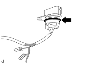
Coat the O-ring of the transmission wire with Toyota Genuine ATF WS.
-
Install the transmission wire to the automatic transaxle case sub-assembly with the bolt.
- Torque:
- 5.4 N*m { 55 kgf*cm, 48 in.*lbf }
-
Connect the transmission revolution sensor (NT) connector and transmission revolution sensor (NC) connector.
-
Install the temperature sensor to the transmission valve body assembly with the bolt and temperature sensor clamp.
- Torque:
- 10.8 N*m { 110 kgf*cm, 8 ft.*lbf }
Note
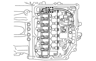
To prevent it from being pinched between the transmission valve body assembly and the transmission case side cover, pass the transmission revolution sensor (NC) wire under the transmission wire (temperature sensor wire) as shown in the illustration.
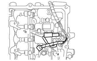
*a Transmission Wire (Temperature Sensor Wire) *b Transmission Revolution Sensor (NC) Wire -
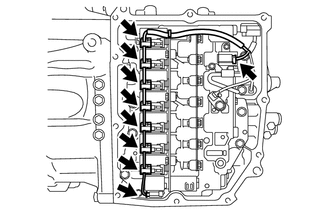
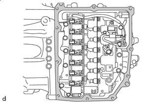
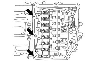
Connect the 9 solenoid valve connectors.
Note

Do not let transmission wire protrude into this area.
-
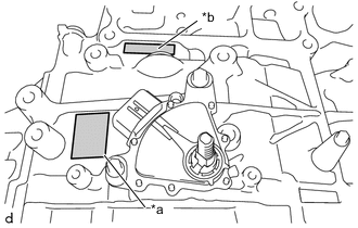
To prevent it from being pinched between the transmission valve body assembly and the transmission case side cover, do not let the transmission wire ride up over the area shown in the illustration.
-
To prevent it from being pinched between the transmission case side cover and the automatic transaxle case sub-assembly, do not let the transmission wire protrude toward the transmission case side cover installation surface.
-
-
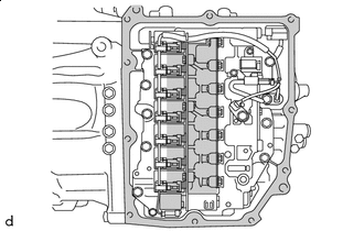
Engage the clamp, and connect the transmission wire to the solenoid lock plate.
-
-
INSTALL TRANSMISSION CASE SIDE COVER (for TMC Made)
Tech Tips
TMC (TOYOTA) Made and AW (AISIN AW) Made components can be identified by the differing locations where the serial number is stamped.
*a TMC Made *b AW Made
-
Area to be cleaned Clean the transmission case side cover installation surface of the automatic transaxle case sub-assembly.
Note
Completely remove any oil or grease from the contact surfaces of the automatic transaxle case sub-assembly.
-
Clean the 3 bolt holes shown in the illustration.
-
*a Adhesive Apply adhesive to 2 or 3 threads on the end of the bolt (A) and 2 bolts (D).
Adhesive Toyota Genuine Adhesive 1324, Three Bond 1324 or equivalent Note
Make sure to install the bolts immediately after applying adhesive to prevent foreign matter from attaching to them.
Tech Tips
The bolt (A) and 2 bolts (D) are in the locations shown in the following step.
-

Temporarily install a new transmission case side cover to the automatic transaxle case sub-assembly with the 2 bolts ((A) and (B)).
Note
-
Bolt (A) is an adhesive-coated bolt.
-
To avoid damaging the gasket, prevent it from contacting the surrounding area during installation procedures.
-
-
Temporarily install the 6 bolts (C) and 2 bolts (D).
Note
Bolt (D) is an adhesive-coated bolt.
-
Operate the engine support bridge and the jack to lower the engine and automatic transaxle assembly.
-
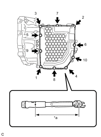
*a Torque Wrench Fulcrum Length Fully tighten the 10 bolts in the order shown in the illustration.
- Torque:
- Specified tightening torque for Bolt (A) and Bolt (D)
- 6.5 N*m { 66 kgf*cm, 58 in.*lbf }
- Specified tightening torque for Bolt (B) and Bolt (C)
- 7.0 N*m { 71 kgf*cm, 62 in.*lbf }
Tech Tips
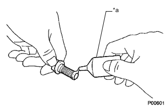
-
If a socket wrench will not fit, use a union nut wrench.
-
Calculate the torque wrench reading when changing the fulcrum length of the torque wrench.
-
When using a union nut wrench (fulcrum length of 22 mm (0.866 in.)) + torque wrench (fulcrum length of 162 mm (6.38 in.)) Bolt (A) and Bolt(D):
5.7 N*m (58 kgf*cm, 50 in.*lbf)
-
When using a union nut wrench (fulcrum length of 22 mm (0.866 in.)) + torque wrench (fulcrum length of 162 mm (6.38 in.)) Bolt (B) and Bolt (C):
6.2 N*m (63 kgf*cm, 55 in.*lbf)
-
Tighten the engine mounting insulator LH with the nut.
- Torque:
- 95 N*m { 969 kgf*cm, 70 ft.*lbf }
-
Tighten the front engine mounting insulator assembly with the bolt.
- Torque:
- 87 N*m { 887 kgf*cm, 64 ft.*lbf }
-
Connect the transmission wire connector.
-
-
INSTALL TRANSMISSION CASE SIDE COVER (for AISIN AW Made)
Tech Tips
TMC (TOYOTA) Made and AW (AISIN AW) Made components can be identified by the differing locations where the serial number is stamped.
*a TMC Made *b AW Made
-
Area to be cleaned Clean the transmission case side cover installation surface of the automatic transaxle case sub-assembly.
Note
Completely remove any oil or grease from the contact surfaces of the automatic transaxle case sub-assembly.
-
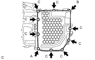
Temporarily install a new transmission case side cover to the automatic transaxle case sub-assembly with the 2 bolts (A and B).
Note
To avoid damaging the gasket, prevent it from contacting the surrounding area during installation procedures.
-
Temporarily install the 8 bolts (C).
-
Operate the engine support bridge and the jack to lower the engine and automatic transaxle assembly.
-
*a Torque Wrench Fulcrum Length Fully tighten the 10 bolts in the order shown in the illustration.
- Torque:
- Specified tightening torque
- 7.0 N*m { 71 kgf*cm, 62 in.*lbf }
Tech Tips
-
If a socket wrench will not fit, use a union nut wrench.
-
Calculate the torque wrench reading when changing the fulcrum length of the torque wrench.
-
When using a union nut wrench (fulcrum length of 22 mm (0.866 in.)) + torque wrench (fulcrum length of 162 mm (6.38 in.)):
6.2 N*m (63 kgf*cm, 55 in.*lbf)
-
Tighten the engine mounting insulator LH with the nut.
- Torque:
- 95 N*m { 969 kgf*cm, 70 ft.*lbf }
-
Tighten the front engine mounting insulator assembly with the bolt.
- Torque:
- 87 N*m { 887 kgf*cm, 64 ft.*lbf }
-
Connect the transmission wire connector.
-
-
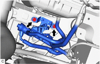
CONNECT OIL COOLER UNION SUB-ASSEMBLY
-
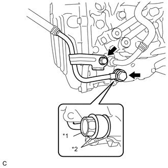
*1 Oil Cooler Union Bolt *2 Gasket Pass the oil cooler union sub-assembly through 2 new gaskets and temporarily install it to the automatic transaxle case sub-assembly.
-
Temporarily install the oil cooler union sub-assembly bracket portion to the automatic transaxle case sub-assembly with the bolt.
-
Fully tighten the oil cooler union bolt.
- Torque:
- 22.6 N*m { 230 kgf*cm, 17 ft.*lbf }
-
Fully tighten the bolt.
- Torque:
- 12 N*m { 122 kgf*cm, 9 ft.*lbf }
-
-
CONNECT OUTLET NO. 1 OIL COOLER HOSE
-
CONNECT TRANSMISSION OIL THERMOSTAT
-
Connect the transmission oil thermostat to the front frame assembly with the 2 bolts.
- Torque:
- 19.5 N*m { 199 kgf*cm, 14 ft.*lbf }
-
-
REMOVE ENGINE SUPPORT BRIDGE
-
REMOVE ENGINE HANGER
-
INSTALL WIRE HARNESS CLAMP BRACKET
-
INSTALL AIR SURGE TANK TO INTAKE MANIFOLD GASKET
-
INSTALL INTAKE AIR SURGE TANK ASSEMBLY
-
CONNECT PURGE VALVE (PURGE VSV)
-
INSTALL THROTTLE BODY WITH MOTOR ASSEMBLY
-
CONNECT VENTILATION HOSE
-
INSTALL BATTERY
-
INSTALL AIR CLEANER ASSEMBLY WITH AIR CLEANER HOSE
-
INSTALL INLET AIR CLEANER ASSEMBLY
-
INSTALL COOL AIR INTAKE DUCT SEAL
-
INSTALL RADIATOR SIDE SEAL RH
-
INSTALL RADIATOR SIDE DEFLECTOR SEAL LH
-
INSTALL OUTER COWL TOP PANEL SUB-ASSEMBLY
-
INSTALL WINDSHIELD WIPER MOTOR AND LINK ASSEMBLY
-
CONNECT CABLE TO NEGATIVE BATTERY TERMINAL
Note
When disconnecting the cable, some systems need to be initialized after the cable is reconnected.
-
ADD AUTOMATIC TRANSAXLE FLUID
-
INSTALL FRONT FENDER APRON SEAL LH
-
INSTALL FRONT FENDER APRON SEAL RH
-
INSTALL FRONT FENDER LINER LH
-
INSTALL FRONT FENDER LINER RH
-
INSTALL NO. 1 ENGINE UNDER COVER
-
INSTALL V-BANK COVER SUB-ASSEMBLY
-
INSTALL FRONT WHEELS