STEERING GEAR(When Using the Engine Support Bridge for AWD) INSTALLATION

PROCEDURE
-
INSTALL TIE ROD ASSEMBLY LH
-
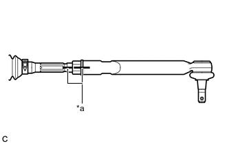
*a Matchmark Install the lock nut and tie rod assembly LH to the steering gear assembly until the matchmarks are aligned.
Tech Tips
After adjusting the toe-in, tighten the lock nut.
-
-
INSTALL TIE ROD ASSEMBLY RH
Tech Tips
Perform the same procedure as for the LH side.
-
TEMPORARILY INSTALL STEERING LINK ASSEMBLY
-
Temporarily install the steering link assembly to the vehicle body.
Note
Use wire or an equivalent tool to secure the steering link assembly.
-
-
INSTALL FRONT FRAME ASSEMBLY
-
INSTALL STEERING LINK ASSEMBLY
-
Install the steering link assembly to the front frame assembly with the 2 bolts and 2 nuts.
- Torque:
- 70 N*m { 714 kgf*cm, 52 ft.*lbf }
Note
-
Make sure to tighten the bolts starting from the steering link assembly pinion shaft side.
-
Keep the nut from rotating while turning the bolt because the nut has its own stopper.
-
-
INSTALL FRONT STABILIZER BAR WITH FRONT STABILIZER LINK ASSEMBLY
-
Install the front stabilizer bar with front stabilizer link assembly to the front frame assembly.
-
-
INSTALL FRONT NO. 1 STABILIZER BRACKET LH
-
INSTALL FRONT NO. 1 STABILIZER BRACKET RH
Tech Tips
Perform the same procedure as for the LH side.
-
INSTALL FRONT STABILIZER LINK ASSEMBLY LH
-
INSTALL FRONT STABILIZER LINK ASSEMBLY RH
Tech Tips
Perform the same procedure as for the LH side.
-
CONNECT TIE ROD ASSEMBLY LH
-
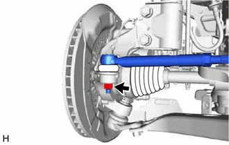
Connect the tie rod assembly LH to the steering knuckle with the nut.
- Torque:
- 49 N*m { 500 kgf*cm, 36 ft.*lbf }
Note
-
Do not damage the ball joint dust cover.
-
Further tighten the nut up to 60° if the holes for the cotter pin are not aligned.
-
Install a new cotter pin.
-
-
CONNECT TIE ROD ASSEMBLY RH
Tech Tips
Perform the same procedure as for the LH side.
-
CONNECT STEERING INTERMEDIATE SHAFT ASSEMBLY
-
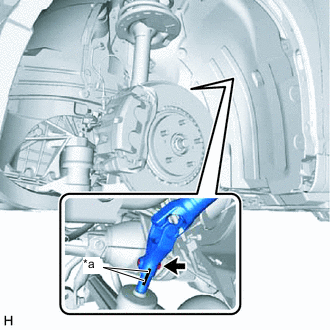
*a Matchmark Align the matchmarks on the steering intermediate shaft assembly and steering link assembly.
-
Connect the steering intermediate shaft assembly to the steering link assembly.
-
Install a new bolt.
- Torque:
- 35.3 N*m { 360 kgf*cm, 26 ft.*lbf }
-
-
INSTALL NO. 2 ENGINE UNDER COVER
-
INSTALL FRONT WHEELS
- Torque:
- 103 N*m { 1050 kgf*cm, 76 ft.*lbf }
-
INSPECT AND ADJUST FRONT WHEEL ALIGNMENT
-
INSPECT STEERING WHEEL CENTER POINT