VACUUM PUMP INSTALLATION
PROCEDURE
-
INSTALL VACUUM PUMP ASSEMBLY
-
When using a new vacuum pump assembly:
-
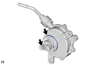

Engine oil Apply engine oil to the 2 O-rings which are installed to a new vacuum pump assembly.
-
-
When reusing the vacuum pump assembly:
-
Engine oil Apply engine oil to 2 new O-rings and install them to the vacuum pump assembly.
-
-
Apply engine oil to the inner surface of the installation hole.
-
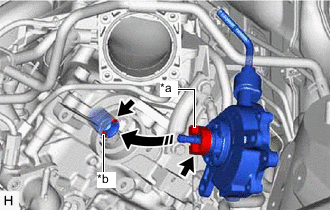
*a Coupling Teeth *b Groove Install the vacuum pump assembly so that the oil pipe engages with the hole of the camshaft and the coupling teeth with the grooves on the camshaft tip.
Note
-
Ensure that the vacuum pump assembly is installed securely.
-
Be careful not to pinch the O-ring.
-
-
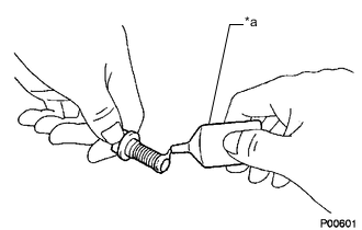
*a Adhesive Apply adhesive to 3 or more threads at the tip of 1 of 3 new bolts.
Adhesive Toyota Genuine Adhesive 1324, Three Bond 1324 or equivalent -
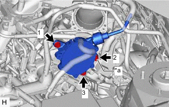
*a Bolt with Adhesive Applied Install the vacuum pump assembly with the 3 bolts.
- Torque:
- 21 N*m { 214 kgf*cm, 15 ft.*lbf }
Note
-
Ensure that the bolt with adhesive applied is installed to the location shown in the illustration.
-
After installation, check that there are no gaps between the matching surfaces and that the vacuum pump assembly is not installed at an angle.
-
Tighten the 3 bolts in the order shown in the illustration.
-
-
INSTALL ENGINE WIRE
-
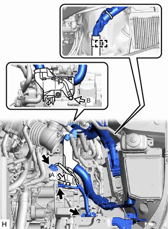
Connector 
Bolt 
Nut Install the engine wire with the bolt (A) and nut.
-
Install the bolt (B).
- Torque:
- 19.1 N*m { 195 kgf*cm, 14 ft.*lbf }
-
Connect the 3 connectors.
-
Engage the clamp.
-
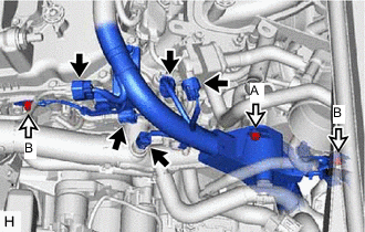
Connector Bolt Install the bolt (A).
-
Install the 2 bolts (B).
- Torque:
- 8.5 N*m { 87 kgf*cm, 75 in.*lbf }
-
Connect the 5 connectors.
-
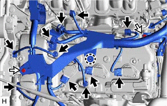
Connector Bolt Install the 2 bolts.
-
Engage the claw.
-
Connect the 11 connectors.
-
Engage the clamp.
-
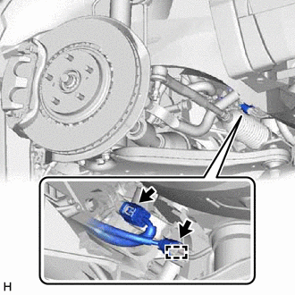
Connect the 2 connectors.
-
-
INSTALL NO. 2 ENGINE UNDER COVER
-
CONNECT HEATER WATER HOSE
-
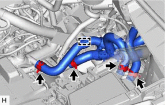
Connect the 4 heater water hoses, and slide the 4 clips to secure them.
-
Engage the clamp.
-
-
CONNECT VENTILATION HOSE
-
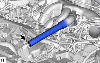
Connect the ventilation hose, and slide the clip to secure it.
-
-
CONNECT AIR TUBE
-
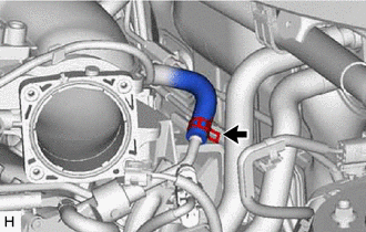
Connect the air tube to the vacuum pump assembly, and slide the clip to secure it.
-
-
INSTALL TRANSMISSION CONTROL CABLE ASSEMBLY
-
Install a new clip to the No. 1 transmission control cable bracket.
-
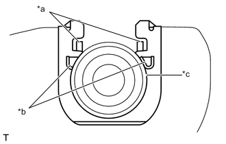
*a Claw A *b Claw B *c Transmission Control Cable Assembly Connect the transmission control cable assembly to the No. 1 transmission control cable bracket.
Note
-
Make sure that the claws A on the clip are securely fit into the No. 1 transmission control cable bracket holes.
-
Make sure that the transmission control cable assembly is securely installed inside of the claws B of the clip.
-
-
Connect the transmission control cable assembly to the transmission control shaft lever and install the clip.
Note
Before connecting the transmission control cable assembly, check that the park/neutral position switch assembly and the shift lever are in neutral.
-
-
INSTALL AIR CLEANER CASE SUB-ASSEMBLY
-
INSTALL AIR CLEANER FILTER ELEMENT SUB-ASSEMBLY
-
INSTALL INLET AIR CLEANER ASSEMBLY
-
INSTALL V-BANK COVER SUB-ASSEMBLY
-
INSTALL COOL AIR INTAKE DUCT SEAL
-
INSTALL RADIATOR SIDE SEAL RH
-
INSTALL RADIATOR SIDE DEFLECTOR SEAL LH
-
INSTALL FRONT WHEEL LH
- Torque:
- 103 N*m { 1050 kgf*cm, 76 ft.*lbf }
-
CONNECT CABLE TO NEGATIVE BATTERY TERMINAL
Note
When disconnecting the cable, some systems need to be initialized after the cable is reconnected.
-
INSTALL THROTTLE BODY WITH MOTOR ASSEMBLY
-
INSPECT VACUUM PUMP OPERATION
-
INSTALL OUTER COWL TOP PANEL SUB-ASSEMBLY
for LHD: Click here
for RHD: Click here
-
INSTALL WINDSHIELD WIPER MOTOR AND LINK ASSEMBLY