FRONT SUSPENSION MEMBER(When Using the Engine Support Bridge for 2GR-FKS) INSTALLATION

PROCEDURE
-
INSTALL HOLE PLUG
-
Install the 10 hole plugs to the front frame assembly.
Tech Tips
There are 2 different shapes of hole plug.
-
-
INSTALL FRONT SUSPENSION MEMBER BODY MOUNTING REAR CUSHION LH
-
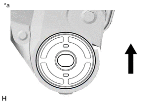
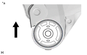
*a View from Underneath 
Front of the Vehicle Temporarily install a new front suspension member body mounting rear cushion LH while confirming the installation direction.
Note
Position the front suspension member body mounting rear cushion LH in the correct direction.
-
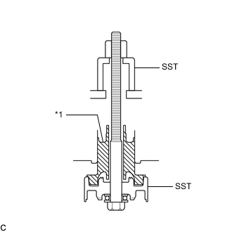
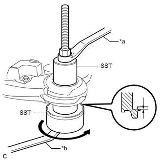
*1 Front Suspension Member Body Mounting Rear Cushion LH Install SST as shown in the illustration.
- SST
- 09830-10010 ( 09830-01010, 09830-01020, 09830-01030, 09830-01060 )
-
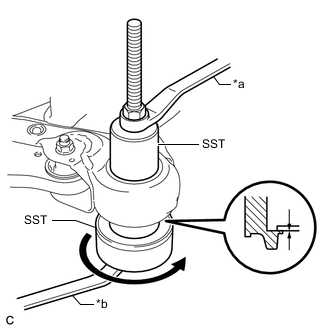
*a Hold *b Turn Using SST, install the front suspension member body mounting rear cushion LH as shown in the illustration.
Note
Check that there is no clearance between the front frame assembly and the front suspension member body mounting rear cushion LH.
-
-
INSTALL FRONT SUSPENSION MEMBER BODY MOUNTING REAR CUSHION RH
-
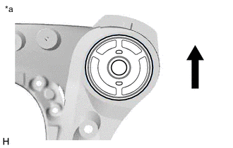
*a View from Underneath Front of the Vehicle Temporarily install a new front suspension member body mounting rear cushion RH while confirming the installation direction.
Note
Position the front suspension member body mounting rear cushion RH in the correct direction.
-
Install SST using the same procedure as for the front suspension member body mounting rear cushion LH.
- SST
- 09830-10010 ( 09830-01010, 09830-01020, 09830-01030, 09830-01060 )
-
Using SST, install the front suspension member body mounting rear cushion RH.
- SST
- 09830-10010 ( 09830-01010, 09830-01020, 09830-01030, 09830-01060 )
Tech Tips
Perform the same procedure as for the LH side.
-
-
INSTALL FRONT SUSPENSION MEMBER BODY MOUNTING FRONT CUSHION
-
*a View from Underneath Front of the Vehicle Temporarily install a new front suspension member body mounting front cushion while confirming the installation direction.
Note
Position the front suspension member body mounting front cushion in the correct direction.
-
Install SST using the same procedure as for the front suspension member body mounting rear cushion LH.
- SST
- 09830-10010 ( 09830-01010, 09830-01020, 09830-01030, 09830-01060 )
-
*a Hold *b Turn Using SST, install each front suspension member body mounting front cushion as shown in the illustration.
- SST
- 09830-10010 ( 09830-01010, 09830-01020, 09830-01030, 09830-01060 )
Note
Check that there is no clearance between the front frame assembly and the front suspension member body mounting front cushion.
-
-
INSTALL FRONT SUSPENSION MEMBER BODY MOUNTING REAR STOPPER
-
Install the 2 front suspension member body mounting rear stoppers to the front frame assembly.
-
-
INSTALL FRONT SUSPENSION MEMBER BODY MOUNTING FRONT STOPPER
-
Install the 2 front suspension member body mounting front stoppers to the front frame assembly.
-
-
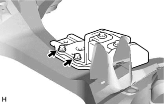
INSTALL NO. 2 FRAME CROSSMEMBER DYNAMIC DAMPER
-
for 2WD:
-
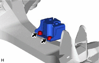
Install the No. 2 frame crossmember dynamic damper to the front frame assembly with the 2 bolts.
- Torque:
- 29 N*m { 296 kgf*cm, 21 ft.*lbf }
-
-
for AWD:
-
Install the No. 2 frame crossmember dynamic damper to the front frame assembly with the 2 bolts.
- Torque:
- 29 N*m { 296 kgf*cm, 21 ft.*lbf }
-
-
-
INSTALL FRONT LOWER NO. 1 SUSPENSION ARM SUB-ASSEMBLY LH
-
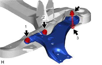
Install the front lower No. 1 suspension arm sub-assembly LH to the front frame assembly with the 3 bolts and nut in the order shown in the illustration.
- Torque:
- Bolt (1), (2)
- 200 N*m { 2039 kgf*cm, 148 ft.*lbf }
- Bolt (3)
- 135 N*m { 1377 kgf*cm, 100 ft.*lbf }
Note
Because the nut has its own stopper, do not turn the nut. Tighten the bolt with the nut secured.
-
-
INSTALL FRONT LOWER NO. 1 SUSPENSION ARM SUB-ASSEMBLY RH
Tech Tips
Perform the same procedure as for the LH side.
-
INSTALL STEERING LINK ASSEMBLY (for 2WD)
-
Install the steering link assembly to the front frame assembly with the 2 bolts and 2 nuts.
- Torque:
- 70 N*m { 714 kgf*cm, 52 ft.*lbf }
Note
-
Make sure to tighten the bolts starting from the steering link assembly pinion shaft side.
-
Keep the nut from rotating while turning the bolt because the nut has its own stopper.
-
-
INSTALL FRONT STABILIZER BAR WITH FRONT STABILIZER LINK ASSEMBLY (for 2WD)
-
Install the front stabilizer bar with 2 front No. 2 stabilizer brackets, 2 front No. 1 stabilizer bar bushings and 2 front stabilizer link assemblies to the front frame assembly.
-
-
INSTALL FRONT NO. 1 STABILIZER BRACKET LH (for 2WD)
-
Install the front No. 1 stabilizer bracket LH to the front frame assembly with the 2 bolts.
- Torque:
- 29 N*m { 296 kgf*cm, 21 ft.*lbf }
-
-
INSTALL FRONT NO. 1 STABILIZER BRACKET RH (for 2WD)
Tech Tips
Perform the same procedure as for the LH side.
-
INSTALL FRONT FRAME ASSEMBLY
-
Slowly jack up the front frame assembly with an engine lifter using 4 attachments or equivalent tools.
CAUTION:
-
The front frame assembly is a very heavy component. Make sure that it is supported securely.
-
If the front frame assembly is not securely supported, it may drop, resulting in serious injury.
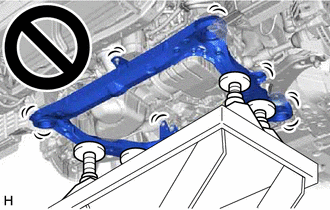
Note
Use attachments to keep the front frame assembly level.
-
-
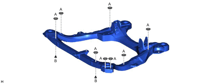
Install the front frame assembly to the vehicle body.
-
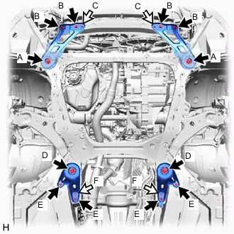
Bolt 
Nut Install the frame side rail plate sub-assembly RH and frame side rail plate sub-assembly LH with the 6 bolts and 2 nuts.
- Torque:
- Bolt (A)
- 85 N*m { 867 kgf*cm, 63 ft.*lbf }
- Bolt (B)
- 32 N*m { 326 kgf*cm, 24 ft.*lbf }
- Nut (C)
- 32 N*m { 326 kgf*cm, 24 ft.*lbf }
-
Install the front suspension member bracket sub-assembly RH and front suspension member bracket sub-assembly LH with the 6 bolts and 2 nuts.
- Torque:
- Bolt (D)
- 85 N*m { 867 kgf*cm, 63 ft.*lbf }
- Bolt (E)
- 32 N*m { 326 kgf*cm, 24 ft.*lbf }
- Nut (F)
- 32 N*m { 326 kgf*cm, 24 ft.*lbf }
-
Lower the engine lifter.
-
-
REMOVE BELT
for 2WD: Click here
for AWD: Click here
-
REMOVE ENGINE SUPPORT BRIDGE
for 2WD: Click here
for AWD: Click here
-
REMOVE ENGINE HANGERS
for 2WD: Click here
for AWD: Click here
-
CONNECT FRONT ENGINE MOUNTING INSULATOR ASSEMBLY
-
Connect the front engine mounting insulator assembly to the front frame assembly with the 3 nuts.
- Torque:
- 58 N*m { 591 kgf*cm, 43 ft.*lbf }
-
Install the hole plug.
-
-
CONNECT ENGINE MOUNTING INSULATOR LH
-
Connect the engine mounting insulator LH to the front frame assembly with the 3 nuts.
- Torque:
- 99 N*m { 1010 kgf*cm, 73 ft.*lbf }
-
Install the 2 hole plugs.
-
-
CONNECT ENGINE MOUNTING INSULATOR RH
-
Connect the engine mounting insulator RH to the front frame assembly with the 3 nuts.
- Torque:
- 99 N*m { 1010 kgf*cm, 73 ft.*lbf }
-
Install the 2 hole plugs.
-
-
CONNECT REAR ENGINE MOUNTING INSULATOR ASSEMBLY
-
Connect the rear engine mounting insulator assembly to the front frame assembly with the 2 nuts.
- Torque:
- 58 N*m { 591 kgf*cm, 43 ft.*lbf }
-
Install the 2 hole plugs.
-
-
CONNECT TRANSMISSION OIL THERMOSTAT
-
Connect the transmission oil thermostat to the front frame assembly with the 2 bolts.
- Torque:
- 19.5 N*m { 199 kgf*cm, 14 ft.*lbf }
-
-
INSTALL STEERING LINK ASSEMBLY (for AWD)
-
INSTALL FRONT STABILIZER BAR WITH FRONT STABILIZER LINK ASSEMBLY (for AWD)
-
INSTALL FRONT NO. 1 STABILIZER BRACKET LH (for AWD)
-
Install the front No. 1 stabilizer bracket LH to the front frame assembly with the 2 bolts.
- Torque:
- 29 N*m { 296 kgf*cm, 21 ft.*lbf }
-
-
INSTALL FRONT NO. 1 STABILIZER BRACKET RH (for AWD)
Tech Tips
Perform the same procedure as for the LH side.
-
CONNECT FRONT LOWER NO. 1 SUSPENSION ARM SUB-ASSEMBLY LH
-
CONNECT FRONT LOWER NO. 1 SUSPENSION ARM SUB-ASSEMBLY RH
Tech Tips
Perform the same procedure as for the LH side.
-
CONNECT TIE ROD ASSEMBLY LH
-
CONNECT TIE ROD ASSEMBLY RH
Tech Tips
Perform the same procedure as for the LH side.
-
CONNECT STEERING INTERMEDIATE SHAFT ASSEMBLY
-
CONNECT FRONT STABILIZER LINK ASSEMBLY LH
-
CONNECT FRONT STABILIZER LINK ASSEMBLY RH
Tech Tips
Perform the same procedure as for the LH side.
-
TEMPORARILY TIGHTEN PROPELLER WITH CENTER BEARING SHAFT ASSEMBLY (for AWD)
-
FULLY TIGHTEN PROPELLER WITH CENTER BEARING SHAFT ASSEMBLY (for AWD)
-
INSTALL FRONT EXHAUST PIPE ASSEMBLY
-
INSTALL NO. 1 EXHAUST PIPE SUPPORT BRACKET (for Lower Side)
-
INSTALL FRONT NO. 3 EXHAUST PIPE SUB-ASSEMBLY
-
INSTALL WIRE HARNESS CLAMP BRACKET
for 2WD: Click here
for AWD: Click here
-
INSTALL AIR SURGE TANK TO INTAKE MANIFOLD GASKET
-
INSTALL INTAKE AIR SURGE TANK ASSEMBLY
-
CONNECT PURGE VALVE (PURGE VSV)
-
CONNECT VENTILATION HOSE
-
INSTALL BRAKE MASTER CYLINDER RESERVOIR ASSEMBLY (for LHD)
-
CONNECT ENGINE WIRE
-
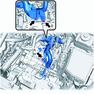
Connect the engine wire to the automatic transaxle case sub-assembly with the 2 bolts and nut.
- Torque:
- Bolt (A)
- 25.5 N*m { 260 kgf*cm, 19 ft.*lbf }
- Bolt (B)
- 19.1 N*m { 195 kgf*cm, 14 ft.*lbf }
- Nut (C)
- 8.5 N*m { 87 kgf*cm, 75 in.*lbf }
-
-
INSTALL BATTERY
-
INSTALL THROTTLE BODY GASKET
-
INSTALL THROTTLE BODY WITH MOTOR ASSEMBLY
-
INSTALL AIR CLEANER ASSEMBLY WITH AIR CLEANER HOSE
-
INSTALL INLET AIR CLEANER ASSEMBLY
-
INSTALL COOL AIR INTAKE DUCT SEAL
-
INSTALL RADIATOR SIDE SEAL RH
-
INSTALL RADIATOR SIDE DEFLECTOR SEAL LH
-
INSTALL OUTER COWL TOP PANEL SUB-ASSEMBLY
for LHD: Click here
for RHD: Click here
-
INSTALL WINDSHIELD WIPER MOTOR AND LINK ASSEMBLY
-
CONNECT CABLE TO NEGATIVE BATTERY TERMINAL
Note
When disconnecting the cable, some systems need to be initialized after the cable is reconnected.
-
ADD ENGINE COOLANT
-
INSPECT FOR COOLANT LEAK
-
WARM UP ENGINE
-
INSPECT FOR EXHAUST GAS LEAK
-
INSPECT AND ADJUST TRANSFER OIL (for AWD)
-
INSTALL FRONT FENDER APRON SEAL LH
-
INSTALL FRONT FENDER APRON SEAL RH
-
INSTALL FRONT FENDER LINER LH
-
INSTALL FRONT FENDER LINER RH
-
INSTALL FRONT FLOOR COVER LH
-
INSTALL NO. 2 ENGINE UNDER COVER
-
INSTALL NO. 1 ENGINE UNDER COVER
-
INSTALL V-BANK COVER SUB-ASSEMBLY
-
INSTALL FRONT WHEELS
- Torque:
- 103 N*m { 1050 kgf*cm, 76 ft.*lbf }
-
INSPECT AND ADJUST FRONT WHEEL ALIGNMENT
-
CHECK FOR SPEED SENSOR SIGNAL