REAR DIFFERENTIAL CARRIER ASSEMBLY INSTALLATION

CAUTION / NOTICE / HINT
Note
If installing a new rear differential carrier assembly, remove the 2 differential side seal caps before installing the rear drive shaft assembly.
PROCEDURE
-
TEMPORARILY INSTALL NO. 1 REAR DIFFERENTIAL SUPPORT
-
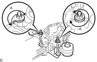
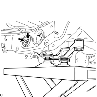
Temporarily install the No. 1 rear differential support to the rear differential carrier assembly with 2 new bolts and 2 new nuts.
Note
-
Be sure to install the No. 1 rear differential support facing the direction shown in the illustration.
-
Be sure to install the tab of each nut to the position (A) shown in the illustration.
Tech Tips
The nuts have tabs to prevent them from rotating.
-
-
-
INSTALL UPPER REAR DIFFERENTIAL MOUNT STOPPER
-
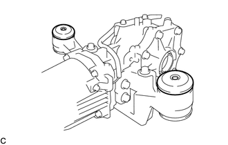
Install the 2 upper rear differential mount stoppers to the No. 1 rear differential support.
Note
Keep the upper rear differential mount stoppers free of oil and foreign matter.
-
-
INSTALL DIFFERENTIAL SUPPORT
-
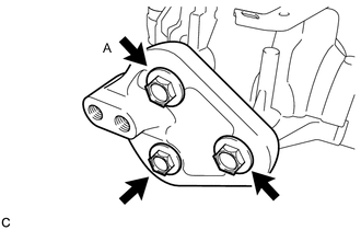
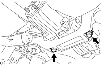
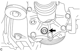
Install the differential support to the rear differential carrier assembly with 3 new bolts.
- Torque:
- 166.7 N*m { 1700 kgf*cm, 123 ft.*lbf }
Note
Tighten the bolt (A) shown in the illustration first.
-
-
TEMPORARILY INSTALL REAR DIFFERENTIAL CARRIER ASSEMBLY WITH DIFFERENTIAL SUPPORT
Note
-
Do not damage the contact surface when installing the rear differential carrier assembly with differential support.
-
The remaining oil may leak out when installing the rear differential carrier assembly with differential support.
-
Securely support the rear differential carrier assembly with differential support while performing this step to avoid excessively tilting or dropping the rear differential carrier assembly with differential support.
-
Install the bolts and nuts with the rear differential carrier assembly with differential support secured.
-
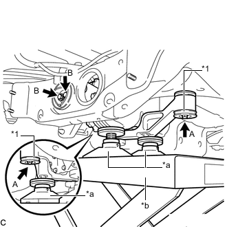
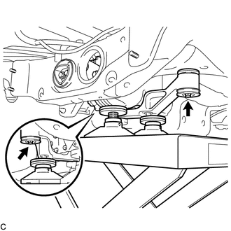
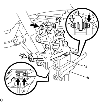
*1 Lower Rear Differential Mount Stopper *a Attachment *b Engine Lifter Support the rear differential carrier assembly with differential support with an engine lifter using 3 attachments or equivalent tools as shown in the illustration.
-
Temporarily install the rear differential carrier assembly with differential support to the front side of the rear suspension member sub-assembly with the 2 lower rear differential mount stoppers, 2 new bolts (A) and 2 new nuts.
Note
-
Be sure to install the lower rear differential mount stoppers with the convex side facing upward.
-
Keep the bolt (A) and lower rear differential mount stoppers free of oil and foreign matter.
Tech Tips
The nuts have tabs to prevent them from rotating.
-
-
Temporarily install the rear differential carrier assembly with differential support to the rear side of the rear suspension member sub-assembly with the 2 new bolts (B).
-
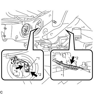
*1 Vacuum Hose *2 Clamp *a Connector Connect the vacuum hose to the 2 clamps, connect the connector, and install the clamp to the connector bracket.
-
-
FULLY INSTALL REAR DIFFERENTIAL CARRIER ASSEMBLY WITH DIFFERENTIAL SUPPORT
Note
Do not tighten the bolts with the inner cylinder or rear differential mount cushion tilted.
-
Tighten the 2 bolts.
- Torque:
- 95.1 N*m { 970 kgf*cm, 70 ft.*lbf }
-
Tighten the 2 bolts.
- Torque:
- 86 N*m { 877 kgf*cm, 63 ft.*lbf }
Tech Tips
-
Tighten the bolts only if the No. 1 rear differential support has been removed from the rear differential carrier assembly.
-
Lower the engine lifter to the extent that the bolts can still be tightened.
-
Tighten the 2 bolts.
- Torque:
- 80 N*m { 816 kgf*cm, 59 ft.*lbf }
-
Lower the engine lifter.
-
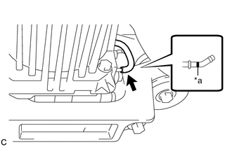
*a Paint Mark Connect the vacuum hose to the electro magnetic control coupling sub-assembly.
Note
Connect the vacuum hose until it reaches the paint mark.
-
-
INSTALL REAR STABILIZER BAR
-
INSTALL STABILIZER LINK SUB-ASSEMBLY LH
-
INSTALL STABILIZER LINK SUB-ASSEMBLY RH
-
INSTALL TAIL EXHAUST PIPE ASSEMBLY
-
TEMPORARILY TIGHTEN PROPELLER WITH CENTER BEARING SHAFT ASSEMBLY
-
FULLY TIGHTEN PROPELLER WITH CENTER BEARING SHAFT ASSEMBLY
-
INSPECT AND ADJUST TRANSFER OIL
-
REMOVE REAR AXLE CARRIER SUB-ASSEMBLY LH
-
*a Wooden Block *b Jack *c Spacer 
Bolt 
Nut Using a jack and wooden block, jack up the rear No. 2 suspension arm assembly LH to replicate standard vehicle height conditions.
CAUTION:
Do not jack up the rear No. 2 suspension arm assembly LH too high as the vehicle may fall.
-
Remove the 4 bolts, 3 nuts and spacer to remove the rear axle carrier sub-assembly LH from the rear No. 1 suspension arm assembly LH, rear No. 2 suspension arm assembly LH, rear upper control arm assembly LH and rear lower shock absorber bracket sub-assembly LH.
-
-
INSTALL REAR DRIVE SHAFT SNAP RING LH
-
INSTALL REAR DRIVE SHAFT ASSEMBLY LH
-
REMOVE REAR AXLE CARRIER SUB-ASSEMBLY RH
Tech Tips
Use the same procedure for the RH side and LH side.
-
INSTALL REAR DRIVE SHAFT SNAP RING RH
-
INSTALL REAR DRIVE SHAFT ASSEMBLY RH
-
ADD DIFFERENTIAL OIL
-
When reusing the rear differential carrier assembly:
-
Using a 10 mm hexagon wrench, install a new gasket and the rear differential drain plug.
- Torque:
- 39 N*m { 398 kgf*cm, 29 ft.*lbf }
-
Add differential oil.
-
-
When using a new rear differential carrier assembly:
-
Using a 10 mm hexagon wrench, remove the differential inspection plug and gasket.
-
Add differential oil.
-
-
-
INSPECT DIFFERENTIAL OIL
-
INSTALL DIFFERENTIAL INSPECTION PLUG
-
INSPECT FOR DIFFERENTIAL OIL LEAK
-
INSTALL REAR AXLE CARRIER SUB-ASSEMBLY LH
-
INSTALL REAR AXLE CARRIER SUB-ASSEMBLY RH
-
INSPECT FOR EXHAUST GAS LEAK
-
INSPECT AND ADJUST JOINT ANGLE
-
INSTALL PROPELLER SHAFT GUARD (for Front Side)
-
INSTALL PROPELLER SHAFT GUARD (for Rear Side)
-
INSTALL WIRING HARNESS CLAMP BRACKET
-
INSTALL FRONT CENTER FLOOR COVER
-
INSTALL FRONT FLOOR COVER LH
-
INSTALL NO. 2 ENGINE UNDER COVER