OIL COOLER INSTALLATION
PROCEDURE
-
INSTALL TRANSMISSION OIL THERMOSTAT
-
Install the transmission oil thermostat to the oil cooler stay with the bolt.
- Torque:
- 19.5 N*m { 199 kgf*cm, 14 ft.*lbf }
-
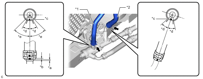
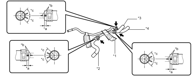
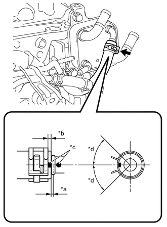
Connect the No. 2 transmission oil cooler hose and outlet No. 2 oil cooler hose to the transmission oil thermostat with each paint mark facing up and slide the 2 clips to secure them.
*1 No. 2 Transmission Oil Cooler Hose *2 Outlet No. 2 Oil Cooler Hose *a 0 to 3 mm (0 to 0.118 in.) *b 2 to 7 mm (0.0787 to 0.276 in.) *c Paint Mark *d 30° (Paint Mark Location) *e 45° (Claw of Clip Location) - - Note
-
Make sure to slide the No. 2 transmission oil cooler hose and outlet No. 2 oil cooler hose until each contacts the hose stopper of the transmission oil thermostat.
-
Make sure that each paint mark and the claws of each clip are within the location shown in the illustration.
-
-
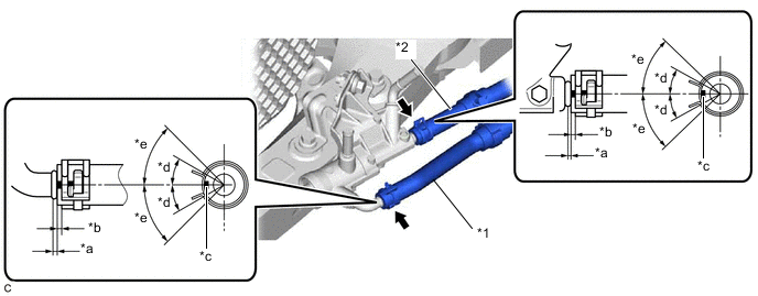
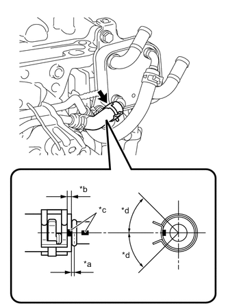
Install the No. 1 transmission oil cooler hose and outlet No. 1 oil cooler hose to the transmission oil thermostat with each paint mark facing the front of the vehicle and slide the 2 clips to secure them.
*1 No. 1 Transmission Oil Cooler Hose *2 Outlet No. 1 Oil Cooler Hose *a 0 to 3 mm (0 to 0.118 in.) *b 2 to 7 mm (0.0787 to 0.276 in.) *c Paint Mark *d 30° (Paint Mark Location) *e 45° (Claw of Clip Location) - - Note
-
Make sure to slide the No. 1 transmission oil cooler hose and outlet No. 1 oil cooler hose until each contacts the hose stopper of the transmission oil thermostat.
-
Make sure that each paint mark is within the location shown in the illustration.
-
Make sure that the claws of the clip of the No. 1 transmission oil cooler hose are within the location shown in the illustration.
-
-
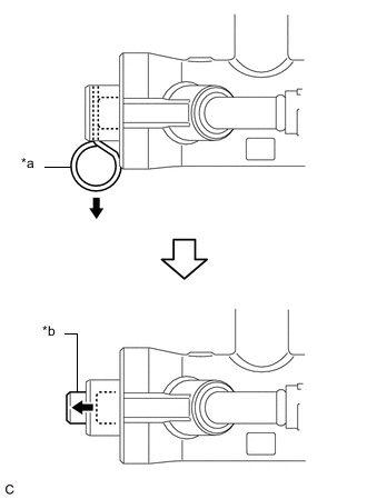
*a Pin *b Shaft When replacing the transmission oil thermostat with a new one:
-
Remove the pin from the transmission oil thermostat.
Note
Make sure that the shaft of the transmission oil thermostat protrudes from the cap after the pin is removed.
-
-
-
INSTALL TRANSMISSION OIL COOLER
-
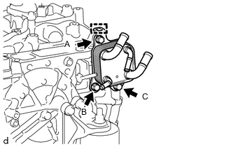
Engage the hook and temporarily install the transmission oil cooler to the automatic transaxle case sub-assembly with the bolt (A).
-
Install the bolt (B).
- Torque:
- 13.5 N*m { 138 kgf*cm, 10 ft.*lbf }
-
Install the bolt (C).
- Torque:
- 13.5 N*m { 138 kgf*cm, 10 ft.*lbf }
-
Fully tighten the bolt (A) to install the transmission oil cooler.
- Torque:
- 13.5 N*m { 138 kgf*cm, 10 ft.*lbf }
-
-
INSTALL NO. 1 OIL COOLER TUBE SUB-ASSEMBLY WITHOUT HOSE
-
Install the inlet No. 1 oil cooler hose, inlet No. 2 oil cooler hose and outlet No. 3 oil cooler hose to the No. 1 oil cooler tube sub-assembly without hose and slide the 3 clips to secure them.
*1 No. 1 Oil Cooler Tube Sub-assembly without Hose *2 Inlet No. 1 Oil Cooler Hose *3 Inlet No. 2 Oil Cooler Hose *4 Outlet No. 3 Oil Cooler Hose *a 2 to 7 mm (0.0787 to 0.276 in.) *b Paint Mark *c 45° (Claw of Clip Location) - - Note
-
Make sure to slide the inlet No. 1 oil cooler hose, inlet No. 2 oil cooler hose and outlet No. 3 oil cooler hose until each contacts the hose stopper of the No. 1 oil cooler tube sub-assembly without hose.
-
Make sure to align the paint mark of each hose with the paint mark of each tube.
-
Make sure that the claws of each clip are within the location shown in the illustration.
-
-
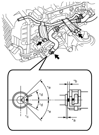
*a 0 to 3 mm (0 to 0.118 in.) *b 2 to 7 mm (0.0787 to 0.276 in.) *c Paint Mark (Left Side of Vehicle) *d 30° (Paint Mark Location) *e 45° (Claw of Clip Location) Install the No. 1 oil cooler tube sub-assembly without hose to the automatic transaxle case sub-assembly and engine mounting bracket LH with the 2 bolts.
- Torque:
- 13.5 N*m { 138 kgf*cm, 10 ft.*lbf }
-
Connect the inlet No. 1 oil cooler hose to the connector tube and slide the clip to secure it.
Note
-
Make sure to slide the inlet No. 1 oil cooler hose until it contacts the hose stopper of the connector tube.
-
Make sure that the paint mark of the inlet No. 1 oil cooler hose and claws of the clip are within the location shown in the illustration.
-
-
-
CONNECT NO. 1 TRANSMISSION OIL COOLER HOSE
-
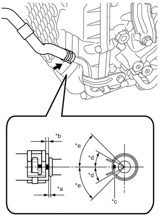
*a 0 to 3 mm (0 to 0.118 in.) *b 2 to 7 mm (0.0787 to 0.276 in.) *c Paint Mark (Left Side of Vehicle) *d 30° (Paint Mark Location) *e 45° (Claw of Clip Location) Connect the No. 1 transmission oil cooler hose to the oil cooler union sub-assembly and slide the clip to secure it.
Note
-
Make sure to slide the No. 1 transmission oil cooler hose until it contacts the hose stopper of the oil cooler union sub-assembly.
-
Make sure that the paint mark of the No. 1 transmission oil cooler hose and claws of the clip are within the location shown in the illustration.
-
-
-
CONNECT OUTLET NO. 1 OIL COOLER HOSE
-
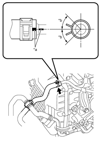
*a Paint Mark *b 45° (Claw of Clip Location) Connect the outlet No. 1 oil cooler hose to the No. 1 oil cooler tube sub-assembly without hose and slide the clip to secure it.
Note
-
Make sure to slide the outlet No. 1 oil cooler hose until it contacts the hose stopper of the No. 1 oil cooler tube sub-assembly without hose.
-
Make sure to align the paint mark of the outlet No. 1 oil cooler hose with the paint mark of the No. 1 oil cooler tube sub-assembly without hose.
-
Make sure that the claws of the clip are within the location shown in the illustration.
-
-
Install the transmission oil cooler tube clamp.
-
-
CONNECT OUTLET NO. 3 OIL COOLER HOSE
-
*a 0 to 3 mm (0 to 0.118 in.) *b 2 to 7 mm (0.0787 to 0.276 in.) *c Paint Mark *d 45° (Claw of Clip Location) Connect the outlet No. 3 oil cooler hose to the transmission oil cooler and slide the clip to secure it.
Note
-
Make sure to slide the outlet No. 3 oil cooler hose until it contacts the hose stopper of the transmission oil cooler.
-
Make sure to align the paint mark of the outlet No. 3 oil cooler hose with paint mark of the transmission oil cooler.
-
Make sure that the claws of the clip are within the location shown in the illustration.
-
-
-
CONNECT INLET NO. 2 OIL COOLER HOSE
-
*a 0 to 3 mm (0 to 0.118 in.) *b 2 to 7 mm (0.0787 to 0.276 in.) *c Paint Mark *d 45° (Claw of Clip Location) Connect the inlet No. 2 oil cooler hose to the transmission oil cooler and slide the clip to secure it.
Note
-
Make sure to slide the inlet No. 2 oil cooler hose until it contacts the hose stopper of the transmission oil cooler.
-
Make sure to align the paint mark of the inlet No. 2 oil cooler hose with the paint mark of the transmission oil cooler.
-
Make sure that the claws of the clip are within the location shown in the illustration.
-
-
-
CONNECT NO. 3 WATER BY-PASS HOSE
-
Connect the No. 3 water by-pass hose to the transmission oil cooler and slide the clip to secure it.
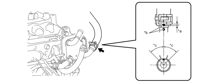
*a 2 to 7 mm (0.0787 to 0.276 in.) *b Paint Mark *c 45° (Claw of Clip Location) - - Note
-
Make sure to slide the No. 3 water by-pass hose until it contacts the hose stopper of the transmission oil cooler.
-
Make sure to align the paint mark of the No. 3 water by-pass hose with the paint mark of the transmission oil cooler.
-
Make sure that the claws of the clip are within the location shown in the illustration.
-
-
-
CONNECT NO. 4 WATER BY-PASS HOSE
-
Connect the No. 4 water by-pass hose to the transmission oil cooler and slide the clip to secure it.
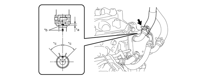
*a 2 to 7 mm (0.0787 to 0.276 in.) *b Paint Mark *c 45° (Claw of Clip Location) - - Note
-
Make sure to slide the No. 4 water by-pass hose until it contacts the hose stopper of the transmission oil cooler.
-
Make sure to align the paint mark of the No. 4 water by-pass hose with the paint mark of the transmission oil cooler.
-
Make sure that the claws of the clip are within the location shown in the illustration.
-
-
-
INSTALL BATTERY
-
INSTALL AIR CLEANER ASSEMBLY WITH AIR CLEANER HOSE
-
INSTALL INLET AIR CLEANER ASSEMBLY
-
INSTALL COOL AIR INTAKE DUCT SEAL
-
INSTALL RADIATOR SIDE SEAL RH
-
INSTALL RADIATOR SIDE DEFLECTOR SEAL LH
-
CONNECT CABLE TO NEGATIVE BATTERY TERMINAL
Note
When disconnecting the cable, some systems need to be initialized after the cable is reconnected.
-
ADD ENGINE COOLANT
-
ADJUST AUTOMATIC TRANSAXLE FLUID
-
INSPECT FOR OIL LEAK
-
INSPECT FOR COOLANT LEAK
-
INSTALL FRONT FENDER APRON SEAL LH
-
INSTALL NO. 1 ENGINE UNDER COVER
-
INSTALL FRONT WHEEL LH
- Torque:
- 103 N*m { 1050 kgf*cm, 76 ft.*lbf }