AUTOMATIC TRANSAXLE FLUID HIGH TEMPERATURE ADJUSTMENT

CAUTION / NOTICE / HINT
CAUTION:
-
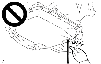
Be careful not to burn yourself when the temperature of the automatic transaxle fluid is high.
-
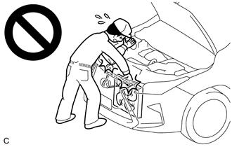
To prevent injury due to contact with an operating V-ribbed belt or cooling fan, keep your hands and clothing away from the V-ribbed belt and cooling fans when working in the engine compartment with the engine running or the ignition switch turned to ON.
PROCEDURE
-
ADJUST AUTOMATIC TRANSAXLE FLUID LEVEL AT HIGH TEMPERATURE
-
Warm up the engine and then turn the ignition switch off.
-
Check the automatic transaxle fluid temperature.
-
Connect the GTS to the DLC3 with the ignition switch off.
-
Turn the ignition switch to ON and turn the GTS on.
Note
To reduce load, make sure that all electrical systems, such as the air conditioning, lighting system, electric fan and audio system are off.
-
Enter the following menus: Powertrain / Transmission / Data List / Engine Speed and A/T Oil Temperature No.1.
Powertrain > Transmission > Data ListTester Display Engine Speed A/T Oil Temperature No.1 Note
-
If the automatic transaxle fluid temperature tends to decrease when the automatic transaxle fluid temperature is between 85°C (185°F) and 90°C (194°F) with the engine idling, make sure that automatic transaxle fluid temperature is above 90°C (194°F) before starting work.
-
If the automatic transaxle fluid temperature tends to increase when the automatic transaxle fluid temperature is between 85°C (185°F) and 90°C (194°F) with the engine idling, make sure that automatic transaxle fluid temperature is below 85°C (185°F) before starting work.
-
If the automatic transaxle fluid temperature tends not to change when the automatic transaxle fluid temperature is between 85°C (185°F) and 90°C (194°F) with the engine idling, make sure that automatic transaxle fluid temperature is 87.5°C (189.5°F) before starting work.
-
-
-
Depress and hold the brake pedal.
-
Start the engine.
-
Slowly move the shift lever from P to D, and then back to P.
Tech Tips
-
Slowly move the shift lever to circulate the automatic transaxle fluid through each part of the automatic transaxle assembly.
-
Keep the shift lever in each position for approximately 3 seconds.
-
-
Lift the vehicle.
Note
Set the vehicle on a lift so that the vehicle is kept level when it is lifted up (make sure the tilt angle from the front to rear and side to side of the vehicle is within +/- 1°).
-
Remove the No. 1 engine under cover.
-
Remove the front fender apron seal LH.
-
Remove the refill plug and gasket from the automatic transaxle case sub-assembly.
-
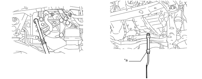
*a SST (Filler Plug Adapter) Install SST (filler plug adapter) to the refill plug hole.
- SST
- 09993-19025 ( 09993-10010, 09993-01030 )
-
*a SST (Vacuum Regulator) Connect SST (vacuum regulator) to SST (filler plug adapter).
- SST
- 09993-19025 ( 09993-10010, 09993-01020 )
-
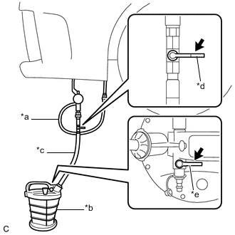
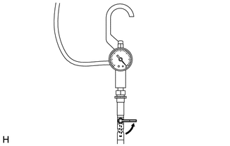
*a SST (Vacuum Regulator) *b SST (Tank Assy) *c Hose of SST (Tank Assy) *d Valve Handle (Upper Valve) *e Valve Handle (Lower Valve) Connect the hose of SST (tank assy) to SST (vacuum regulator).
- SST
- 09993-19025 ( 09993-20010 )
Note
Ensure both of the valves of SST (tank assy) are closed by turning the valve handle (upper valve) and valve handle (lower valve) to the position shown in the illustration so they are perpendicular to the hoses.
-
Connect a compressed air hose to SST (tank assy).
Note
Do not apply 689 kPa (7.0 kgf/cm2, 100 psi) or more of compressed air to SST (tank assy).
-

Open the lower valve of SST (tank assy) by turning the valve handle (lower valve) so it is in-line with the compressed air hose.
-
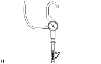
Open the upper valve of SST (tank assy) by turning the valve handle (upper valve) so it is in-line with the hose of SST (tank assy).
Note
-
Make sure to turn the valve handle (upper valve) slowly.
-
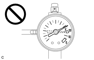
Make sure the value on the gauge of SST (vacuum regulator) stays between -10 and -20 kPa (-0.1 and -0.2 kgf/cm2, -1.5 and -2.9 psi).
-
If the value on the gauge of SST (vacuum regulator) exceeds -20 kPa (-0.2 kgf/cm2, -2.9 psi), make sure to turn the valve handle (upper valve) so it is perpendicular to the hose of SST (tank assy) immediately, otherwise parts inside the automatic transaxle assembly may be damaged.
Tech Tips
Vacuum will be applied to the automatic transaxle assembly when both of the valves of SST (tank assy) are opened to prevent automatic transaxle fluid loss when removing/installing the overflow plug.
-
-
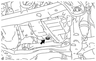
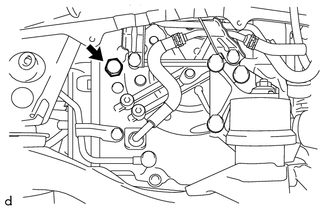
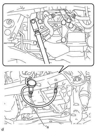
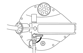
Using a 10 mm hexagon socket wrench, remove the overflow plug and gasket from the transaxle housing.
CAUTION:
A small amount of hot automatic transaxle fluid may leak from the overflow plug port during removal.
Tech Tips
Place a container under the overflow plug to collect any automatic transaxle fluid that leaks out.
-
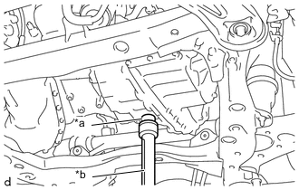
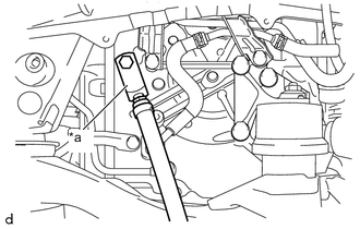
*a SST (Adapter 18) *b SST (Overflow Level Gauge) Install SST (adapter 18) to SST (overflow level gauge) and then install SST (overflow level gauge) to the overflow plug hole by hand until it is fully seated against the transaxle housing.
- SST
- 09993-01100
- 09993-19025 ( 09993-10010, 09993-01010 )
Note
Ensure that the sliding tube of SST (overflow level gauge) is fully retracted into the housing of SST (overflow lever gauge) before inserting it into the overflow plug hole.
Tech Tips
The level/measurement indicator on SST (overflow level gauge) will read 0 mm (0 in.) when the sliding tube of SST (overflow level gauge) is fully retracted.
-
Adjust SST (overflow level gauge) to the specified measurement according to the table below and lock the sliding scale of SST (overflow level gauge) by tightening the thumb screw.
Specified Measurement Specified Measurement at Automatic Transaxle Fluid Temperature of 85 to 90°C (185 to 194°F) Engine Idle Speed (rpm) 600 to 800 80 mm (3.15 in.) Note
Before proceeding with the inspection, make sure the automatic transaxle fluid temperature is between 85 to 90°C (185 to 194°F) and the engine idle speed is within the specified range in the table above.
-
Close the upper valve of SST (tank assy) by turning the valve handle (upper valve) so it is perpendicular to the hose of SST (tank assy).
Note
-
Make sure to turn the valve handle (upper valve) slowly.
-
Make sure that the gauge of SST (vacuum regulator) reads 0 kPa (0 kgf/cm2, 0 psi).
Tech Tips
Vacuum that was applied to the automatic transaxle assembly will not be applied when the valve handle (upper valve) is closed.
-
-
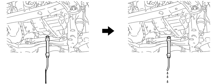
Check the automatic transaxle fluid flowing from the hose at the bottom of SST (overflow level gauge).
-
If the amount of automatic transaxle fluid that comes out of SST (overflow level gauge) is large, proceed to step [#1].
-
If no automatic transaxle fluid comes out of SST (overflow level gauge), proceed to step [#2].
-
-
If the amount of automatic transaxle fluid that comes out of SST (overflow level gauge) is large. [#1]
-
Wait until the automatic transaxle fluid flow slows and only drips come out.
Tech Tips
The automatic transaxle fluid flow will not stop completely because the automatic transaxle fluid continues to expand as its temperature increases.
-
Open the upper valve of SST (tank assy) by turning the valve handle (upper valve) so it is in-line with the hose of SST (tank assy).
Note
-
Make sure to turn the valve handle (upper valve) slowly.
-
Make sure the value on the gauge of SST (vacuum regulator) stays between -10 and -20 kPa (-0.1 and -0.2 kgf/cm2, -1.5 and -2.9 psi).
-
If the value on the gauge of SST (vacuum regulator) exceeds -20 kPa (-0.2 kgf/cm2, -2.9 psi), make sure to turn the valve handle (upper valve) so it is perpendicular to the hose of SST (tank assy) immediately, otherwise parts inside the automatic transaxle assembly may be damaged.
Tech Tips
Vacuum will be applied to the automatic transaxle assembly when both of the valves of SST (tank assy) are opened to prevent automatic transaxle fluid loss when removing/installing the overflow plug.
-
-
Remove SST (overflow level gauge) from the overflow plug hole.
-
Using a 10 mm hexagon socket wrench, install the overflow plug and a new gasket to the transaxle housing.
- Torque:
- 50 N*m { 510 kgf*cm, 37 ft.*lbf }
Note
To prevent the gasket from being deformed when tightening, coat it with Toyota Genuine ATF WS.
-
Close the upper valve of SST (tank assy) by turning the valve handle (upper valve) so it is perpendicular to the hose of SST (tank assy).
Note
-
Make sure to turn the valve handle (upper valve) slowly.
-
Make sure that the gauge of SST (vacuum regulator) reads 0 kPa (0 kgf/cm2, 0 psi).
Tech Tips
Vacuum that was applied to the automatic transaxle assembly will not be applied when the valve handle (upper valve) is closed.
-
-
Close the lower valve of SST (tank assy) by turning the valve handle (lower valve) so it is perpendicular to the compressed air hose.
-
Disconnect the compressed air hose from SST (tank assy).
-
Disconnect the hose of SST (tank assy) from SST (vacuum regulator).
-
Disconnect SST (vacuum regulator) from SST (filler plug adapter).
-
Remove SST (filler plug adapter) from the refill plug hole.
-
-
If no automatic transaxle fluid comes out of SST (overflow level gauge). [#2]
-
*a SST (Filler Plug Adapter) Remove SST (filler plug adapter) from the refill plug hole.
-
Add automatic transaxle fluid through the refill plug hole until fluid comes out of SST (overflow level gauge).
*a SST (Overflow Level Gauge) - - Note
Use Toyota Genuine ATF WS.
-
Wait until the automatic transaxle fluid flow slows and only drips come out.
Tech Tips
The automatic transaxle fluid flow will not stop completely because the automatic transaxle fluid continues to expand as its temperature increases.
-
*a SST (Filler Plug Adapter) Install SST (filler plug adapter) to the refill plug hole.
- SST
- 09993-19025 ( 09993-10010, 09993-01030 )
-
Open the upper valve of SST (tank assy) by turning the valve handle (upper valve) so it is in-line with the hose of SST (tank assy).
Note
-
Make sure to turn the valve handle (upper valve) slowly.
-
Make sure the value on the gauge of SST (vacuum regulator) stays between -10 and -20 kPa (-0.1 and -0.2 kgf/cm2, -1.5 and -2.9 psi).
-
If the value on the gauge of SST (vacuum regulator) exceeds -20 kPa (-0.2 kgf/cm2, -2.9 psi), make sure to turn the valve handle (upper valve) so it is perpendicular to the hose of SST (tank assy) immediately, otherwise parts inside the automatic transaxle assembly may be damaged.
Tech Tips
Vacuum will be applied to the automatic transaxle assembly when both of the valves of SST (tank assy) are opened to prevent automatic transaxle fluid loss when removing/installing the overflow plug.
-
-
Remove SST (overflow level gauge) from the overflow plug hole.
-
Using a 10 mm hexagon socket wrench, install the overflow plug and a new gasket to the transaxle housing.
- Torque:
- 50 N*m { 510 kgf*cm, 37 ft.*lbf }
Note
To prevent the gasket from being deformed when tightening, coat it with Toyota Genuine ATF WS.
-
Close the upper valve of SST (tank assy) by turning the valve handle (upper valve) so it is perpendicular to the hose of SST (tank assy).
Note
-
Make sure to turn the valve handle (upper valve) slowly.
-
Make sure that the gauge of SST (vacuum regulator) reads 0 kPa (0 kgf/cm2, 0 psi).
Tech Tips
Vacuum that was applied to the automatic transaxle assembly will not be applied when the valve handle (upper valve) is closed.
-
-
Close the lower valve of SST (tank assy) by turning the valve handle (lower valve) so it is perpendicular to the compressed air hose.
-
Disconnect the compressed air hose from SST (tank assy).
-
Disconnect the hose of SST (tank assy) from SST (vacuum regulator).
-
Disconnect SST (vacuum regulator) from SST (filler plug adapter).
-
Remove SST (filler plug adapter) from the refill plug hole.
-
-
Install the refill plug and a new gasket to the automatic transaxle case sub-assembly.
- Torque:
- 49 N*m { 500 kgf*cm, 36 ft.*lbf }
Note
To prevent the gasket from being deformed when tightening, coat it with Toyota Genuine ATF WS.
-
Remove the GTS from the DLC3.
-
Lift the vehicle.
-
Clean each part.
-
Check for automatic transaxle fluid leaks.
-
Install the front fender apron seal LH.
-
Install the No. 1 engine under cover.
-
Lower the vehicle.
-