AUTOMATIC TRANSAXLE SYSTEM, Diagnostic DTC:P074015
| DTC Code | DTC Name |
|---|---|
| P074015 | Torque Converter Clutch Circuit Short to Battery or Open |
DESCRIPTION
Refer to DTC P074011.
| DTC No. | Detection Item | DTC Detection Condition | Trouble Area | MIL | Memory | Note |
|---|---|---|---|---|---|---|
| P074015 | Torque Converter Clutch Circuit Short to Battery or Open | 1. Diagnosis Condition 2. Malfunction Status 3. Malfunction Time 4. Other
|
|
Comes on | DTC stored | SAE Code: P2770 |
MONITOR DESCRIPTION
Based on the signals from the throttle position sensor, the air flow meter and the crankshaft position sensor, the ECM sends a signal to solenoid (SL) valve to regulate the hydraulic pressure and provide smoother torque converter engagement. Solenoid (SL) valve responds to commands from the ECM. The valve controls the lock-up relay valve to perform the torque-converter lock-up function. If the ECM detects an open or short to +B in the solenoid (SL) valve circuit, it will illuminate the MIL and store the DTC.
CAUTION / NOTICE / HINT
Note
Perform registration and/or initialization when parts related to the automatic transaxle are replaced.
Tech Tips
After performing repair, clear the DTCs and perform the following procedure to check that DTCs are not output.
-
Perform the D Position Shift Test inspection in Road Test.
-
Turn the ignition switch off.
-
Perform step (1) again.
-
Check for DTCs again.
PROCEDURE
-
INSPECT TRANSMISSION WIRE (SOLENOID (SL) VALVE)
-
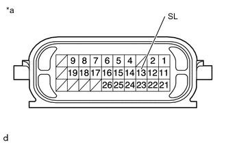
*a Component without harness connected
(Transmission Wire)
Disconnect the C62 transmission wire connector.
-
Measure the resistance according to the value(s) in the table below.
Standard Resistance Tester Connection Condition Specified Condition 13 (SL) - Body ground 20°C (68°F) 11 to 15 Ω 13 (SL) - Other terminals Always 10 kΩ or higher -
Connect the C62 transmission wire connector.
Result Proceed to OK NG
NG 
INSPECT SOLENOID (SL) VALVE Click here
OK 
-
-
CHECK HARNESS AND CONNECTOR (TRANSMISSION WIRE - ECM)
-
Disconnect the C1 ECM connector.
-
Measure the resistance according to the value(s) in the table below.
Standard Resistance Tester Connection Condition Specified Condition C1-62 (SL) - Body ground 20°C (68°F) 11 to 15 Ω C1-62 (SL) - Other terminals Always 10 kΩ or higher Result Proceed to OK NG
NG 
REPAIR OR REPLACE HARNESS OR CONNECTOR (TRANSMISSION WIRE - ECM)
OK
-
-
REPLACE ECM
-
Replace the ECM.
Result Proceed to NEXT
NEXT
PERFORM REGISTRATION Click here
-
-
INSPECT SOLENOID (SL) VALVE
-
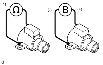
*1 Solenoid (SL) Valve Remove the solenoid (SL) valve.
-
Measure the resistance according to the value(s) in the table below.
Standard Resistance Tester Connection Condition Specified Condition Solenoid (SL) valve connector terminal - Solenoid (SL) valve body 20°C (68°F) 11 to 15 Ω -
Connect a positive (+) lead from the battery to the terminal of the solenoid valve connector, and a negative (-) lead to the solenoid body. Check that the valve moves and makes an operating sound.
OK Valve moves and makes an operating sound. Result Proceed to OK NG
OK
REPAIR OR REPLACE TRANSMISSION WIRE When Not Using the Engine Support Bridge: Click here
REPAIR OR REPLACE TRANSMISSION WIRE When Using the Engine Support Bridge: Click hereNG
REPLACE SOLENOID (SL) VALVE Click here
-