LANE DEPARTURE ALERT SYSTEM, Diagnostic DTC:C1AA7
| DTC Code | DTC Name |
|---|---|
| C1AA7 | Skid Control Buzzer Circuit |
DESCRIPTION
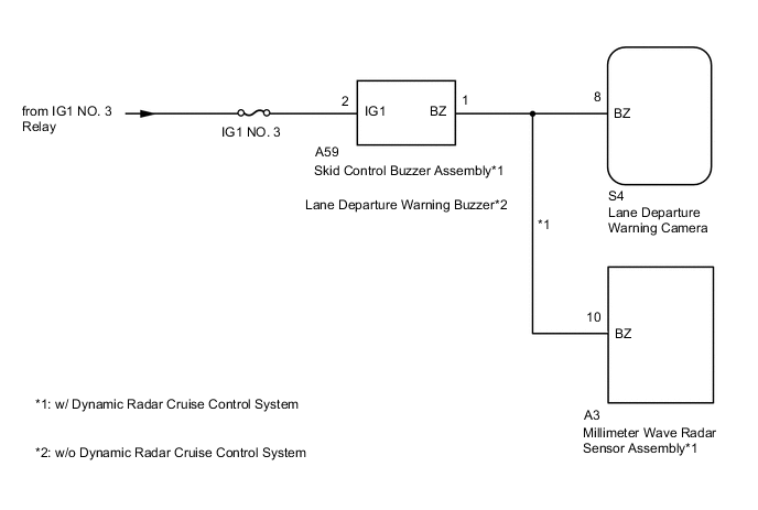
The lane departure warning camera sends a buzzer request signal to the skid control buzzer assembly*1 or lane departure warning buzzer*2 to sound the buzzer. When the lane departure warning camera detects a malfunction in the buzzer circuit, the lane departure warning camera stores DTC C1AA7.
| DTC No. | Detection Item | DTC Detection Condition | Trouble Area |
|---|---|---|---|
| C1AA7 | Skid Control Buzzer Circuit | When IG voltage is 8 to 16 V and both of the following conditions are met:
|
|
-
*1: w/ Dynamic Radar Cruise Control System
-
*2: w/o Dynamic Radar Cruise Control System
WIRING DIAGRAM
CAUTION / NOTICE / HINT
Note
-
When the lane departure warning camera is replaced with a new one, adjustment of the lane departure warning camera axis must be performed.
-
Inspect the fuses for circuits related to this system before performing the following procedure.
PROCEDURE
-
CONFIRM MODEL
-
Choose the model to be inspected.
Result Result Proceed to w/ Dynamic Radar Cruise Control System A w/o Dynamic Radar Cruise Control System B
B 
INSPECT LANE DEPARTURE WARNING BUZZER Click here
A 
-
-
INSPECT SKID CONTROL BUZZER ASSEMBLY
-
Remove the skid control buzzer assembly.
-
Inspect the skid control buzzer assembly.
Result Proceed to OK NG
NG 
REPLACE SKID CONTROL BUZZER ASSEMBLY Click here
OK
-
-
CHECK TERMINAL VOLTAGE (POWER SOURCE OF SKID CONTROL BUZZER ASSEMBLY)
-

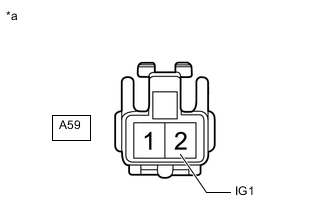
*a Front view of wire harness connector
(to Skid Control Buzzer Assembly)
Disconnect the A59 skid control buzzer assembly connector.
-
Measure the voltage according to the value(s) in the table below.
Standard Voltage Tester Connection Condition Specified Condition A59-2 (IG1) - Body ground Engine switch on (IG) 11 to 14 V A59-2 (IG1) - Body ground Engine switch off Below 1 V Result Proceed to OK NG
NG
REPAIR OR REPLACE HARNESS OR CONNECTOR (SKID CONTROL BUZZER ASSEMBLY - BATTERY)
OK
-
-
CHECK HARNESS AND CONNECTOR (SKID CONTROL BUZZER ASSEMBLY - LANE DEPARTURE WARNING CAMERA)
-
Disconnect the A59 skid control buzzer assembly connector.
-
Disconnect the S4 lane departure warning camera connector.
-
Disconnect the A3 millimeter wave radar sensor assembly connector.
-
Measure the resistance according to the value(s) in the table below.
Standard Resistance Tester Connection Condition Specified Condition A59-1 (BZ) - S4-8 (BZ) Always Below 1 Ω A59-1 (BZ) or S4-8 (BZ) - Body ground Always 10 kΩ or higher Result Proceed to OK NG
OK
REPLACE LANE DEPARTURE WARNING CAMERA Click here
NG
REPAIR OR REPLACE HARNESS OR CONNECTOR (SKID CONTROL BUZZER ASSEMBLY - LANE DEPARTURE WARNING CAMERA)
-
-
INSPECT LANE DEPARTURE WARNING BUZZER
-
Remove the lane departure warning buzzer.
-
Inspect the lane departure warning buzzer.
Result Proceed to OK NG
NG
REPLACE LANE DEPARTURE WARNING BUZZER Click here
OK
-
-
CHECK TERMINAL VOLTAGE (POWER SOURCE OF LANE DEPARTURE WARNING BUZZER)
-
*a Front view of wire harness connector
(to Lane Departure Warning Buzzer)
Disconnect the A59 lane departure warning buzzer connector.
-
Measure the voltage according to the value(s) in the table below.
Standard Voltage Tester Connection Condition Specified Condition A59-2 (IG1) - Body ground Engine switch on (IG) 11 to 14 V A59-2 (IG1) - Body ground Engine switch off Below 1 V Result Proceed to OK NG
NG
REPAIR OR REPLACE HARNESS OR CONNECTOR (LANE DEPARTURE WARNING BUZZER - BATTERY)
OK
-
-
CHECK HARNESS AND CONNECTOR (LANE DEPARTURE WARNING BUZZER - LANE DEPARTURE WARNING CAMERA)
-
Disconnect the A59 lane departure warning buzzer connector.
-
Disconnect the S4 lane departure warning camera connector.
-
Measure the resistance according to the value(s) in the table below.
Standard Resistance Tester Connection Condition Specified Condition A59-1 (BZ) - S4-8 (BZ) Always Below 1 Ω A59-1 (BZ) or S4-8 (BZ) - Body ground Always 10 kΩ or higher Result Proceed to OK NG
OK
REPLACE LANE DEPARTURE WARNING CAMERA Click here
NG
REPAIR OR REPLACE HARNESS OR CONNECTOR (LANE DEPARTURE WARNING BUZZER - LANE DEPARTURE WARNING CAMERA)
-