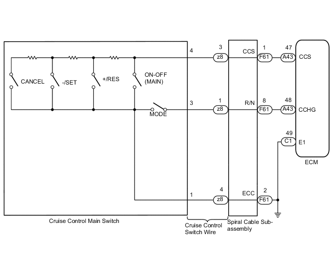
DYNAMIC RADAR CRUISE CONTROL SYSTEM Cruise Control Switch Circuit
DESCRIPTION
The cruise control main switch is used to turn the dynamic radar cruise control system on and off, as well as operate 8 functions: SET, -(COAST), TAP-DOWN, RES (RESUME), + (ACCEL), TAP-UP, CANCEL, and MODE. The SET, TAP-DOWN, and - (COAST) functions, and the RES (RESUME), TAP-UP, and + (ACCEL) functions are operated with the same switch. The cruise control main switch is an automatic return type switch which turns on only while it is being operated in the direction of each arrow and turns off when released. The internal contact points of the cruise control main switch turn on with switch operation. The ECM then reads the voltage value that has been changed by the switch operation to control MODE, SET, -, RES, +, or CANCEL function. The dynamic radar cruise control system has 2 cruise control modes: constant speed control mode and vehicle-to-vehicle distance control mode.
-
Vehicle-to-vehicle distance control mode is selected by default when the dynamic radar cruise control system is turned on using the cruise control main switch (ON-OFF button).
-
The operation of constant speed control mode is the same as that for a conventional cruise control system.
WIRING DIAGRAM
PROCEDURE
-
READ VALUE USING GTS (MAIN SW M-CPU, CANCEL SWITCH, SET/COAST SWITCH, RES/ACC SWITCH)
-
Connect the GTS to the DLC3.
-
Turn the engine switch on (IG).
-
Turn the GTS on.
-
Enter the following menus: Powertrain / Radar Cruise / Data List.
-
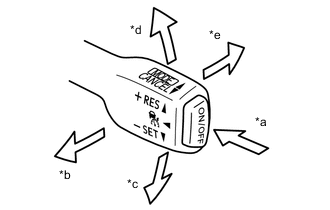
*a ON-OFF *b CANCEL *c -SET *d +RES *e MODE Check the Data List for proper functioning of the cruise control main switch.
Powertrain > Radar Cruise > Data ListTester Display Measurement Item Range Normal Condition Diagnostic Note Main SW M-CPU Cruise control main switch signal (Main CPU) ON or OFF ON: Cruise control main switch on
OFF: Cruise control main switch off
- Cancel Switch CANCEL switch signal ON or OFF ON: CANCEL switch on
OFF: CANCEL switch off
- SET/COAST Switch -/SET switch signal ON or OFF ON: -/SET switch on
OFF: -/SET switch off
- RES/ACC Switch +/RES switch signal ON or OFF ON: +/RES switch on
OFF: +/RES switch off
-
Powertrain > Radar Cruise > Data ListTester Display Main SW M-CPU Cancel Switch SET/COAST Switch RES/ACC Switch OK When the cruise control main switch is operated, the display changes as shown in the table. Result Proceed to OK NG -
Turn the engine switch off.
OK 
PROCEED TO NEXT SUSPECTED AREA SHOWN IN PROBLEM SYMPTOMS TABLE Click here
NG 
-
-
INSPECT CRUISE CONTROL MAIN SWITCH
-
Remove the cruise control main switch.
-
Measure the resistance according to the value(s) in the table below.
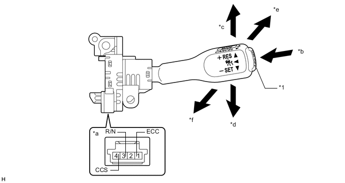
*1 Cruise Control Main Switch (ON-OFF button) - - *a Component without harness connected
(cruise control main switch)
*b ON-OFF *c +/RES *d -/SET *e MODE *f CANCEL Standard Resistance Tester Connection Condition Specified Condition 1 (ECC) - 3 (R/N) Cruise control main switch (ON-OFF button) not pressed 1 MΩ or higher MODE Below 1.5 Ω 1 (ECC) - 4 (CCS) Cruise control main switch (ON-OFF button) not pressed 1 MΩ or higher Cruise control main switch (ON-OFF button) pressed Below 1.5 Ω +/RES 235 to 245 Ω -/SET 617 to 643 Ω CANCEL 1509 to 1571 Ω -
Reinstall the cruise control main switch.
Result Proceed to OK NG
NG
REPLACE CRUISE CONTROL MAIN SWITCH Click here
OK
-
-
CHECK CRUISE CONTROL SWITCH WIRE (SPIRAL CABLE SUB-ASSEMBLY - CRUISE CONTROL MAIN SWITCH)
-
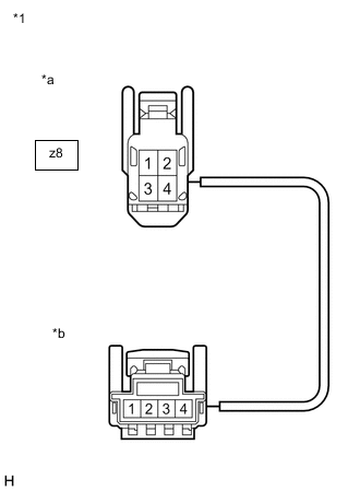
*1 Cruise Control Switch Wire *a Front view of wire harness connector
(to Spiral Cable Sub-assembly)
*b Front view of wire harness connector
(to Cruise Control Main Switch)
Remove the cruise control switch wire.
-
Measure the resistance according to the value(s) in the table below.
Standard Resistance (Check for Open) Tester Connection Condition Specified Condition z8-4 - Cruise control main switch side connector terminal 1 Always Below 1 Ω z8-1 - Cruise control main switch side connector terminal 3 Always Below 1 Ω z8-3 - Cruise control main switch side connector terminal 4 Always Below 1 Ω -
Reinstall the cruise control switch wire.
Result Proceed to OK NG
NG
REPAIR OR REPLACE CRUISE CONTROL SWITCH WIRE Click here
OK
-
-
INSPECT SPIRAL CABLE SUB-ASSEMBLY
-
Inspect the spiral cable sub-assembly.
Result Proceed to OK NG
NG
REPLACE SPIRAL CABLE SUB-ASSEMBLY Click here
OK
-
-
CHECK HARNESS AND CONNECTOR (SPIRAL CABLE SUB-ASSEMBLY - ECM)
-
Disconnect the A43 ECM connector.
-
Disconnect the F61 spiral cable sub-assembly connector.
-
Measure the resistance according to the value(s) in the table below.
Standard Resistance (Check for Open) Tester Connection Condition Specified Condition A43-47 (CCS) - F61-1 (CCS) Always 3 Ω or less A43-48 (CCHG) - F61-8 (R/N) Always 3 Ω or less Standard Resistance (Check for Short) Tester Connection Condition Specified Condition A43-47 (CCS) or F61-1 (CCS) - Body ground Always 1 MΩ or higher A43-48 (CCHG) or F61-8 (R/N) - Body ground Always 1 MΩ or higher -
Reconnect the A43 ECM connector.
-
Reconnect the F61 spiral cable sub-assembly connector.
Result Proceed to OK NG
NG
REPAIR OR REPLACE HARNESS OR CONNECTOR (SPIRAL CABLE SUB-ASSEMBLY - ECM)
OK
-
-
CHECK HARNESS AND CONNECTOR (SPIRAL CABLE SUB-ASSEMBLY - BODY GROUND)
-
Disconnect the F61 spiral cable sub-assembly connector.
-
Measure the resistance according to the value(s) in the table below.
Standard Resistance (Check for Open) Tester Connection Condition Specified Condition F61-2 (ECC) - Body ground Always Below 1 Ω -
Reconnect the F61 spiral cable sub-assembly connector.
Result Proceed to OK NG
OK
PROCEED TO NEXT SUSPECTED AREA SHOWN IN PROBLEM SYMPTOMS TABLE Click here
NG
REPAIR OR REPLACE HARNESS OR CONNECTOR (SPIRAL CABLE SUB-ASSEMBLY - BODY GROUND)
-