ENGINE UNIT INSTALLATION

CAUTION / NOTICE / HINT
PROCEDURE
-
INSTALL ENGINE COOLANT TEMPERATURE SENSOR
-
INSTALL KNOCK CONTROL SENSOR WIRE
-
Engage the 3 clamps.
-
-
INSTALL KNOCK CONTROL SENSOR
-
INSTALL ENGINE OIL PRESSURE SWITCH ASSEMBLY
-
INSTALL NO. 1 VACUUM SWITCHING VALVE
-
Install the No. 1 vacuum switching valve with the bolt.
- Torque:
- 10 N*m { 102 kgf*cm, 7 ft.*lbf }
-
-
INSTALL NO. 2 IDLER PULLEY SUB-ASSEMBLY
-
Install the idler pulley cover plate, No. 2 idler pulley sub-assembly and No. 2 idler pulley cover plate with the bolt.
- Torque:
- 54 N*m { 551 kgf*cm, 40 ft.*lbf }
-
-
INSTALL WATER PUMP PULLEY
-
Temporarily install the water pump pulley with the 4 bolts.
-
Using SST, hold the water pump pulley.
- SST
- 09960-10010 ( 09962-01000, 09963-00700 )
-
Tighten the 4 bolts.
- Torque:
- 21 N*m { 214 kgf*cm, 15 ft.*lbf }
-
-
INSTALL NO. 2 TIMING GEAR COVER
-
Install the No. 2 timing gear cover with the 2 bolts.
- Torque:
- 6.0 N*m { 61 kgf*cm, 53 in.*lbf }
-
-
INSTALL V-RIBBED BELT TENSIONER ASSEMBLY
-
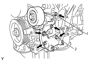
Temporarily install the V-ribbed belt tensioner assembly with the 5 bolts.
Tech Tips
Each bolt length is as follows:
Item Length Bolt (A) 70 mm (2.76 in.) Bolt (B) 33 mm (1.30 in.) -
Install the V-ribbed belt tensioner assembly by tightening the bolt (1) and then the bolt (2).
- Torque:
- 43 N*m { 438 kgf*cm, 32 ft.*lbf }
-
Tighten the other bolts.
- Torque:
- 43 N*m { 438 kgf*cm, 32 ft.*lbf }
-
-
INSTALL REAR ENGINE MOUNTING BRACKET
-
Install the rear engine mounting bracket with the 3 bolts.
- Torque:
- 64 N*m { 653 kgf*cm, 47 ft.*lbf }
-
-
INSTALL ENGINE MOUNTING BRACKET RH
-
Install the engine mounting bracket RH with the 3 bolts.
- Torque:
- 54 N*m { 551 kgf*cm, 40 ft.*lbf }
-
-
INSTALL EXHAUST MANIFOLD TO HEAD GASKET LH
-
INSTALL EXHAUST MANIFOLD SUB-ASSEMBLY LH (TWC: Front Catalyst)
-
INSTALL NO. 2 EXHAUST MANIFOLD HEAT INSULATOR
-
INSTALL NO. 2 MANIFOLD STAY
-
INSTALL NO. 2 ENGINE OIL LEVEL DIPSTICK GUIDE
-
Install a new O-ring to the No. 2 engine oil level dipstick guide.
-
Apply a light coat of engine oil to the O-ring.
-
Push the No. 2 engine oil level dipstick guide end into the engine oil level dipstick guide.
-
Install the No. 2 engine oil level dipstick guide with the bolt.
- Torque:
- 21 N*m { 214 kgf*cm, 15 ft.*lbf }
-
Install the engine oil level dipstick.
-
-
INSTALL EXHAUST MANIFOLD TO HEAD GASKET
-
INSTALL EXHAUST MANIFOLD SUB-ASSEMBLY RH (TWC: Front Catalyst)
-
INSTALL IGNITION COIL ASSEMBLY
-
INSTALL NO. 1 SURGE TANK STAY
Note
Do not apply oil to the bolt listed below:
Oil Application Prohibited Bolt Bolt for No. 1 Surge Tank Stay and Cylinder Head Cover
-
Install the No. 1 surge tank stay with the bolt.
- Torque:
- 21 N*m { 214 kgf*cm, 15 ft.*lbf }
-
-
INSTALL THROTTLE BODY BRACKET
Note
Do not apply oil to the bolt listed below:
Oil Application Prohibited Bolt Bolt for Throttle Body Bracket and Cylinder Head Cover
-
Install the throttle body bracket with the bolt.
- Torque:
- 21 N*m { 214 kgf*cm, 15 ft.*lbf }
-
-
INSTALL INTAKE MANIFOLD
-
INSTALL GENERATOR ASSEMBLY