EXHAUST PIPE INSTALLATION

PROCEDURE
-
INSTALL HEATED OXYGEN SENSOR (for Bank 2)
-
INSTALL FRONT EXHAUST PIPE ASSEMBLY
-
Install a new gasket to the front exhaust pipe assembly.
-
Install the front exhaust pipe assembly to the exhaust manifold assembly LH (TWC: Front Catalyst) with the 2 nuts.
- Torque:
- 43 N*m { 438 kgf*cm, 32 ft.*lbf }
-
Connect the heated oxygen sensor (for Bank 2) connector.
-
Engage the 2 wire harnesses clamps.
-
-
INSTALL NO. 1 EXHAUST PIPE SUPPORT BRACKET (for Lower Side)
-
Install the No. 1 exhaust pipe support bracket (for Lower Side) with the 2 bolts.
- Torque:
- 21 N*m { 214 kgf*cm, 15 ft.*lbf }
-
-
INSTALL HEATED OXYGEN SENSOR (for Bank 1)
-
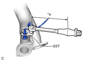
*a Torque Wrench Fulcrum Length Using SST, install the heated oxygen sensor (for Bank 1) to the front No. 3 exhaust pipe sub-assembly.
- SST
- 09224-00012
- Torque:
- Specified tightening torque
- 44 N*m { 449 kgf*cm, 32 ft.*lbf }
Note
If the heated oxygen sensor has been struck or dropped, replace it.
Tech Tips
-
Calculate the torque wrench reading when changing the fulcrum length of the torque wrench.
-
When using SST (fulcrum length of 30 mm (1.18 in.)) + torque wrench (fulcrum length of 180 mm (7.09 in.)):
37.7 N*m (384 kgf*cm, 28 ft.*lbf)
-
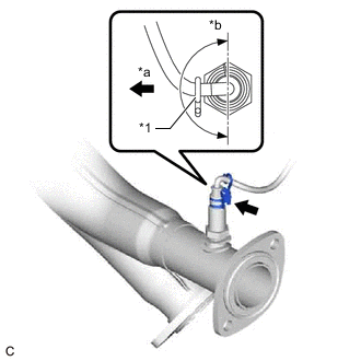
*1 Wire Harness Clamp Bracket *a Left of Vehicle *b 180° Install the wire harness clamp bracket to the heated oxygen sensor (for Bank 1).
Tech Tips
Make sure the direction of the wire harness clamp bracket is as shown in the illustration.
-
-
INSTALL FRONT NO. 3 EXHAUST PIPE SUB-ASSEMBLY
-
Install 2 new gaskets to the front No. 3 exhaust pipe sub-assembly.
-
Install the front No. 3 exhaust pipe sub-assembly to the front exhaust pipe assembly and exhaust manifold (TWC: Front Catalyst) with the 2 bolts and 2 nuts.
- Torque:
- 43 N*m { 438 kgf*cm, 32 ft.*lbf }
-
Connect the heated oxygen sensor (for Bank 1) connector.
-
Engage the 3 wire harness clamps.
-
-
INSTALL CENTER EXHAUST PIPE ASSEMBLY (TWC: Rear Catalyst)
-
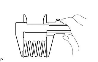
Using a vernier caliper, measure the free length of the 2 compression springs.
Standard Length 43.0 mm (1.69 in.) Minimum Free Length 41.5 mm (1.63 in.) If the free length is less than minimum, replace the compression spring.
-
Temporarily install a new gasket to the front No. 3 exhaust pipe sub-assembly.
-
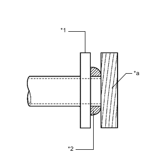
*1 Front No. 3 Exhaust Pipe Sub-assembly *2 Gasket *a Wooden Block Using a plastic hammer and wooden block, tap in the gasket until its surface is flush with the front No. 3 exhaust pipe sub-assembly.
Note
-
Be careful with the installation direction of the gasket.
-
Do not reuse the gasket.
-
Do not damage the gasket.
-
Do not push in the gasket by using the exhaust pipes when connecting them.
-
-
Connect the center exhaust pipe assembly (TWC: Rear Catalyst) to the exhaust pipe support.
-
Install the center exhaust pipe assembly (TWC: Rear Catalyst) to the front No. 3 exhaust pipe sub-assembly with the 2 bolts and 2 compression springs.
- Torque:
- 43 N*m { 438 kgf*cm, 32 ft.*lbf }
Tech Tips
After installation, check that the space between the flanges of the center exhaust pipe assembly (TWC: Rear Catalyst) and front No. 3 exhaust pipe sub-assembly is consistent front-to-rear and left-to-right.
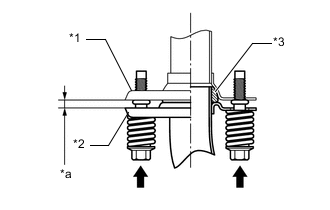
*1 Center Exhaust Pipe Assembly (TWC: Rear Catalyst) *2 Front No. 3 Exhaust Pipe Sub-assembly *3 Gasket *a Space between Flanges: 8.5 mm (0.335 in.)
-
-
INSTALL NO. 3 EXHAUST PIPE DAMPER
-
Install the No. 3 exhaust pipe damper to the tail exhaust pipe assembly with the 2 bolts.
- Torque:
- 19 N*m { 194 kgf*cm, 14 ft.*lbf }
-
-
INSTALL TAIL EXHAUST PIPE ASSEMBLY
-
Install a new gasket to the center exhaust pipe assembly (TWC: Rear Catalyst).
-
Connect the tail exhaust pipe assembly to the 4 exhaust pipe supports.
-
Install the tail exhaust pipe assembly to the center exhaust pipe assembly (TWC: Rear Catalyst) with the 2 bolts.
- Torque:
- 43 N*m { 438 kgf*cm, 32 ft.*lbf }
-
-
INSPECT FOR EXHAUST GAS LEAK
If gas is leaking, tighten the areas necessary to stop the leak. Replace damaged parts as necessary.
-
Perform Inspection After Repair after repairing an exhaust gas leak.
-
-
INSTALL FRONT FLOOR COVER LH
-
INSTALL NO. 2 ENGINE UNDER COVER
-
INSTALL NO. 1 ENGINE UNDER COVER