INTAKE MANIFOLD INSTALLATION
PROCEDURE
-
INSTALL STUD BOLT
Tech Tips
If a stud bolt is deformed or the threads are damaged, replace it.
-
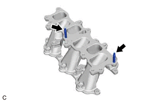
Using an E6 "TORX" socket wrench, install the 2 stud bolts to the intake manifold.
- Torque:
- 10 N*m { 102 kgf*cm, 7 ft.*lbf }
-
-
INSTALL NO. 1 INTAKE MANIFOLD TO HEAD GASKET
-
Install 2 new No. 1 intake manifold to head gaskets to each cylinder head sub-assembly.
Note
-
Align the port holes of the No. 1 intake manifold to head gaskets and cylinder head sub-assembly.
-
Make sure that the No. 1 intake manifold to head gaskets are installed in the correct direction.
-
-
-
INSTALL INTAKE MANIFOLD
-
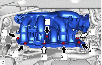
Temporarily install the intake manifold to the cylinder head sub-assembly with the 4 bolts and 4 nuts.
-
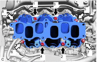

Bolt 
Nut Tighten the 4 bolts and 4 nuts in the order shown in the illustration.
- Torque:
- 21 N*m { 214 kgf*cm, 15 ft.*lbf }
-
-
INSTALL INJECTOR VIBRATION INSULATOR
-
INSTALL NO. 1 DELIVERY PIPE SPACER
-
INSTALL FUEL DELIVERY PIPE WITH SENSOR ASSEMBLY
-
CONNECT FUEL TUBE SUB-ASSEMBLY
-
INSTALL NO. 2 ENGINE MOUNTING STAY RH
-
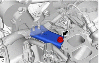
Install the No. 2 engine mounting stay RH to the intake manifold and engine mounting insulator sub-assembly RH with the bolt.
- Torque:
- 21 N*m { 214 kgf*cm, 15 ft.*lbf }
-
Install the wire harness clamp bracket to the No. 2 engine mounting stay RH with the bolt.
- Torque:
- 10 N*m { 102 kgf*cm, 7 ft.*lbf }
-
Engage the wire harness clamp to the wire harness clamp bracket.
-
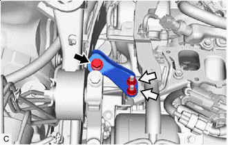
Bolt Nut Install the No. 2 engine mounting stay RH to the engine moving control rod with the bolt and 2 nuts.
- Torque:
- Bolt:
- 38 N*m { 387 kgf*cm, 28 ft.*lbf }
- Nut:
- 23 N*m { 235 kgf*cm, 17 ft.*lbf }
-
-
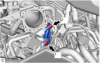
INSTALL NO. 1 V-BANK COVER BRACKET
Tech Tips
Perform this procedure only when replacement of the No. 1 V-bank cover bracket is necessary.
-
Install the 2 No. 1 V-bank cover brackets to the intake air surge tank assembly.
- Torque:
- 9.0 N*m { 92 kgf*cm, 80 in.*lbf }
-
-
INSTALL AIR SURGE TANK TO INTAKE MANIFOLD GASKET
-
Install a new air surge tank to intake manifold gasket to the intake air surge tank assembly.
-
-
INSTALL INTAKE AIR SURGE TANK ASSEMBLY
Note
Do not apply oil to the bolts and nuts as listed below:
Oil Application Prohibited Bolt and Nut Bolt and Nut for Intake Air Surge Tank Assembly and Intake Manifold
-
Temporarily install the intake air surge tank assembly to the intake manifold with the 5 bolts and 2 nuts.
-
Temporarily install the No. 2 surge tank stay to the intake air surge tank assembly and camshaft housing RH with the 2 bolts.
-
Bolt Nut Tighten the 5 bolts and 2 nuts in the order shown in the illustration.
- Torque:
- 21 N*m { 214 kgf*cm, 15 ft.*lbf }
-
Tighten the 2 bolts in the order shown in the illustration.
- Torque:
- 21 N*m { 214 kgf*cm, 15 ft.*lbf }
-
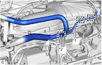
*1 Vacuum Hose Sub-assembly *2 No. 2 Air Tube Engage the clamp to connect the No. 2 air tube to the intake air surge tank assembly.
-
Engage the 2 clamps to connect the vacuum hose sub-assembly to the intake air surge tank assembly.
-
Engage the 2 clamps to connect the vacuum hose sub-assembly to the intake air surge tank assembly.
-
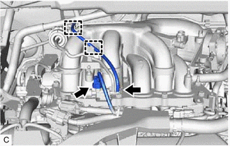
Connect the vacuum switching valve (for ACIS) connector.
-
-
CONNECT PURGE VALVE (PURGE VSV)
-
Connect the purge valve (purge VSV) to the intake air surge tank assembly with the bolt.
- Torque:
- 21 N*m { 214 kgf*cm, 15 ft.*lbf }
-
Connect the No. 1 fuel vapor feed hose to the intake air surge tank assembly.
-
-
CONNECT VENTILATION HOSE
-
Connect the ventilation hose to the intake air surge tank assembly and slide the clip to secure it.
-
-
INSTALL RESERVOIR BRACKET (for RHD)
-
INSTALL BRAKE MASTER CYLINDER RESERVOIR ASSEMBLY (for RHD)
-
INSTALL THROTTLE BODY WITH MOTOR ASSEMBLY
-
INSTALL OUTER COWL TOP PANEL SUB-ASSEMBLY (for LHD)
-
INSTALL OUTER COWL TOP PANEL SUB-ASSEMBLY (for RHD)
-
INSTALL WINDSHIELD WIPER MOTOR AND LINK ASSEMBLY
-
CONNECT CABLE TO NEGATIVE BATTERY TERMINAL
Note
When disconnecting the cable, some systems need to be initialized after the cable is reconnected.
-
INSPECT FOR FUEL LEAK
-
INSTALL V-BANK COVER SUB-ASSEMBLY