FRONT STABILIZER BAR INSTALLATION
PROCEDURE
-
INSTALL FRONT NO. 1 STABILIZER BRACKET LH
-
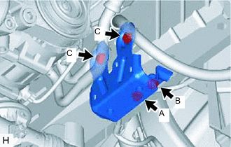
Press the front No. 1 stabilizer bracket LH against the frame toward the outside of the vehicle and temporarily tighten the bolt (A).
-
Install the bolt (B), fully tighten the bolt (A), and then install the 2 bolts (C).
- Torque:
- 49 N*m { 500 kgf*cm, 36 ft.*lbf }
-
for LHD:
-
Install the wire harness clamp to the front No. 1 stabilizer bracket LH.
-
-
for RHD:
-
Install the 2 wire harness clamps to the front No. 1 stabilizer bracket LH.
-
-
-
INSTALL FRONT NO. 1 STABILIZER BRACKET RH
-
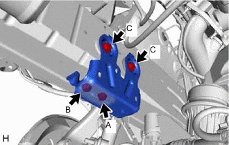
Press the front No. 1 stabilizer bracket RH against the frame toward the outside of the vehicle and temporarily tighten the bolt (A).
-
Install the bolt (B), fully tighten the bolt (A), and then install the 2 bolts (C).
- Torque:
- 49 N*m { 500 kgf*cm, 36 ft.*lbf }
-
for LHD:
-
Install the 2 wire harness clamps to the front No. 1 stabilizer bracket RH.
-
-
for RHD:
-
Install the wire harness clamp to the front No. 1 stabilizer bracket RH.
-
-
-
INSTALL FRONT NO. 1 STABILIZER BAR BUSHING
-
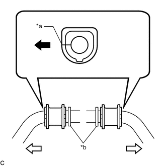
*a Cutout *b Bushing Stopper 
Front of the Vehicle 
Outside of the Vehicle Install the 2 front No. 1 stabilizer bar bushings to the front stabilizer bar as shown in the illustration.
Note
When installing the front No. 1 stabilizer bar bushings, make sure that the cutout faces the front of the vehicle.
-
-
INSTALL FRONT STABILIZER BAR
-
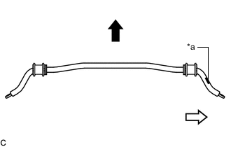
*a Identification Mark Front of the Vehicle RH Side Install the front stabilizer bar to the vehicle so that the identification mark is positioned on the right side of the vehicle.
-
-
INSTALL FRONT NO. 2 STABILIZER BRACKET LH
-
Install the front No. 2 stabilizer bracket LH to the front No. 1 stabilizer bracket LH with the 2 bolts.
- Torque:
- 49 N*m { 500 kgf*cm, 36 ft.*lbf }
-
-
INSTALL FRONT NO. 2 STABILIZER BRACKET RH
Tech Tips
Perform the same procedure as for the LH side.
-
INSTALL REAR ENGINE UNDER COVER LH
-
INSTALL REAR ENGINE UNDER COVER RH
Tech Tips
Perform the same procedure as for the LH side.
-
INSTALL FRONT STABILIZER LINK ASSEMBLY LH
-
Install the front stabilizer link assembly LH to the front stabilizer bar and front lower suspension arm assembly LH with the 2 nuts.
- Torque:
- 84 N*m { 857 kgf*cm, 62 ft.*lbf }
Tech Tips
If the ball joint turns together with the nut, use a 6 mm hexagon wrench to hold the stud bolt.
-
-
INSTALL FRONT STABILIZER LINK ASSEMBLY RH
Tech Tips
Perform the same procedure as for the LH side.
-
INSTALL FRONT UPPER NO. 2 SUSPENSION MEMBER
-
INSTALL ENGINE UNDER COVER
-
INSTALL FRONT WHEELS
- Torque:
- 103 N*m { 1050 kgf*cm, 76 ft.*lbf }
-
INSPECT AND ADJUST FRONT WHEEL ALIGNMENT