SHIFT LEVER POSITION SENSOR INSTALLATION
PROCEDURE
-
INSTALL SHIFT LEVER POSITION SENSOR
Tech Tips
Make sure that the manual shaft has not been rotated prior to installing the shift lever position sensor as the detent spring may become detached from the manual shaft.
-
Temporarily install the shift lever position sensor to the hybrid vehicle transmission assembly with the 2 bolts.
Tech Tips
Tighten the bolt to the specified torque when adjusting the shift lever position sensor.
-
Install a new lock plate and the lock nut to the shift lever position sensor.
- Torque:
- 6.9 N*m { 70 kgf*cm, 61 in.*lbf }
-
Temporarily install the transmission control shaft lever to the shift lever position sensor with the spring washer and nut.
Tech Tips
Tighten the nut to the specified torque when adjusting the shift lever position sensor.
-
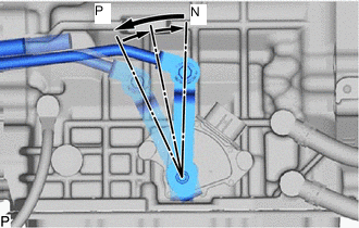
Turn the transmission control shaft lever counterclockwise until it stops, then turn it clockwise 2 notches.
-
Remove the nut, spring washer and transmission control shaft lever from the shift lever position sensor.
-
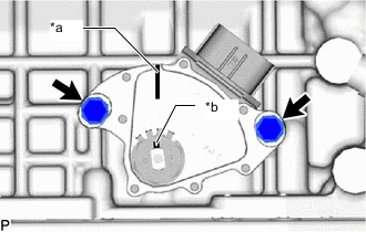
*a Neutral Basic Line *b Groove Align the neutral basic line with the groove as shown in the illustration.
-
Hold the shift lever position sensor in that position and tighten the 2 bolts.
- Torque:
- 5.4 N*m { 55 kgf*cm, 48 in.*lbf }
-
Using a screwdriver, stake the lock nut with the lock plate.
Note
Check that the lock nut is securely installed.
-
Install the transmission control shaft lever with floor shift gear shifting rod sub-assembly to the shift lever position sensor with the nut and spring washer.
- Torque:
- 15.7 N*m { 160 kgf*cm, 12 ft.*lbf }
-
Connect the shift lever position sensor connector.
-
-
INSTALL REAR ENGINE MOUNTING MEMBER
-
Install the rear engine mounting member to the body with the 2 bolts.
- Torque:
- 34.7 N*m { 354 kgf*cm, 26 ft.*lbf }
-
-
INSTALL FLOOR SHIFT GEAR SHIFTING ROD SUB-ASSEMBLY
-
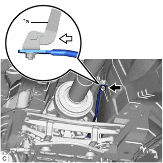
*a Lever 
Pushing the lever rearward Temporarily install the floor shift gear shifting rod sub-assembly to the lever of the transmission floor shift assembly with the nut.
-
Tighten the nut while lightly pushing the lever of the transmission floor shift assembly rearward.
- Torque:
- 12.8 N*m { 131 kgf*cm, 9 ft.*lbf }
Note
Do not push the lever of the transmission floor shift assembly too hard.
-
-
INSTALL PROPELLER WITH CENTER BEARING SHAFT ASSEMBLY
-
INSPECT SHIFT LEVER POSITION SENSOR POSITION
-
ADJUST SHIFT LEVER POSITION SENSOR POSITION
-
INSPECT SHIFT LEVER POSITION
-
ADJUST SHIFT LEVER POSITION
-
INSTALL NO. 2 ENGINE UNDER COVER (w/ No. 2 Engine Under Cover)
-
INSTALL FRONT SUSPENSION MEMBER BRACE