HYBRID VEHICLE TRANSMISSION INSTALLATION
PROCEDURE
-
INSTALL HYBRID VEHICLE TRANSMISSION ASSEMBLY
-
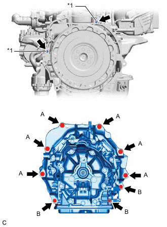
*1 Knock Pin Make sure that the 2 knock pins are installed to the engine assembly.
-
Using a transmission jack, align the engine assembly and hybrid vehicle transmission assembly, fit the knock pins into the knock pin holes, and tighten the 9 bolts.
- Torque:
- Bolt (A)
- 71 N*m { 724 kgf*cm, 52 ft.*lbf }
- Bolt (B)
- 37 N*m { 377 kgf*cm, 27 ft.*lbf }
Note
-
Make sure to align the hybrid vehicle transmission assembly so that the input shaft of the hybrid vehicle transmission assembly will be inserted straight into the inner splines of the transmission input damper assembly.
-
Do not use excess force when installing the hybrid vehicle transmission assembly.
-
When mounting the hybrid vehicle transmission assembly to the engine assembly, make sure to securely fit the knock pins into the knock pin holes.
-
When tightening the bolts, be sure that the contact surfaces of the engine assembly and the hybrid vehicle transmission assembly are in close contact with one another.
-
Do not apply grease either to the inner splines or to the input shaft.
Tech Tips
-
Bolt (A) : 50 mm (1.97 in.)
-
Bolt (B) : 43 mm (1.69 in.)
Bolt Length
-
-
INSTALL OIL COOLER WITHOUT HOSE TUBE SUB-ASSEMBLY
-
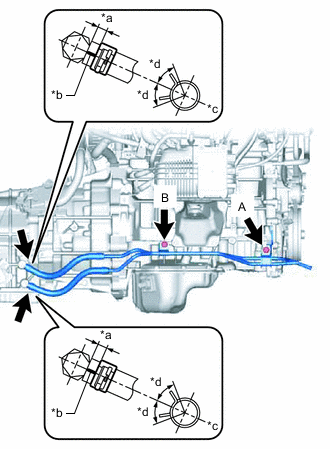
*a 2 to 7 mm (0.0787 to 0.276 in.) *b Marking *c Center of the marking *d Within 45° of the center of the clip Install the oil cooler without hose tube sub-assembly to the engine assembly with the 2 bolts.
- Torque:
- 22 N*m { 224 kgf*cm, 16 ft.*lbf }
Note
Tighten the 2 bolts in the order of (A) and (B).
-
Connect the oil cooler without hose tube sub-assembly to the 2 elbows and slide the 2 clips to secure them.
Note
Install the clip so that the center of the clip is within 45° of the center of the marking of the oil cooler without hose tube sub-assembly as shown in the illustration.
-
-
INSTALL REAR NO. 1 ENGINE MOUNTING INSULATOR
-
INSTALL REAR ENGINE MOUNTING MEMBER
-
INSTALL MOTOR CABLE
-
INSTALL GENERATOR CABLE
-
INSTALL NO. 2 EARTH WIRE
-
Install the No. 2 earth wire to the hybrid vehicle transmission assembly with the bolt.
- Torque:
- 13 N*m { 133 kgf*cm, 10 ft.*lbf }
-
-
INSTALL UPPER TRANSAXLE COVER ASSEMBLY
-
Install the upper transaxle cover assembly to the hybrid vehicle transmission assembly with the bolt.
- Torque:
- 16 N*m { 163 kgf*cm, 12 ft.*lbf }
-
-
INSTALL WIRE HARNESS CLAMP BRACKET
-
Install the 2 wire harness clamp brackets to the hybrid vehicle transmission assembly with the 2 bolts.
- Torque:
- 10 N*m { 102 kgf*cm, 7 ft.*lbf }
-
Install the wire harness clamp bracket to the hybrid vehicle transmission assembly with the bolt.
- Torque:
- 10 N*m { 102 kgf*cm, 7 ft.*lbf }
-
-
CONNECT WIRE HARNESS
-
Connect the 2 clamps and wire harness to the hybrid vehicle transmission assembly.
-
Connect the shift lever position sensor connector.
-
Install the wire harness to the hybrid vehicle transmission assembly with the 3 bolts.
- Torque:
- 10 N*m { 102 kgf*cm, 7 ft.*lbf }
-
Connect the 2 clamps and wire harness to the hybrid vehicle transmission assembly.
-
Connect the motor resolver sensor connector.
-
Connect the generator resolver sensor connector.
-
-
INSTALL MOTOR HEAT INSULATOR
-
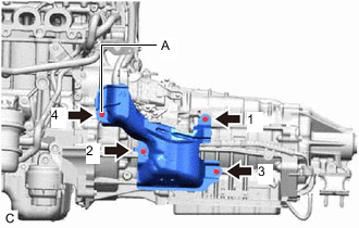
Temporarily install the motor heat insulator to the hybrid vehicle transmission assembly with the 4 bolts.
Note
Temporarily install the bolt (A) first.
-
Tighten the 4 bolts in the order shown in the illustration.
- Torque:
- 8.0 N*m { 82 kgf*cm, 71 in.*lbf }
-
-
INSTALL FLOOR SHIFT GEAR SHIFTING ROD SUB-ASSEMBLY
-
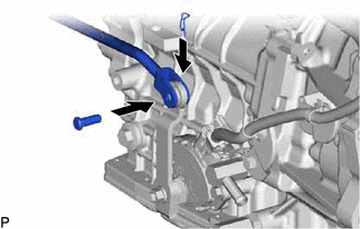
Install the floor shift gear shifting rod sub-assembly to the transmission control shaft lever with the pin.
-
Install a new clip to the pin.
-
-
INSTALL EXHAUST MANIFOLD CONVERTER SUB-ASSEMBLY
-
ADD HYBRID TRANSMISSION FLUID
Note
If installing a new hybrid vehicle transmission assembly, it is not necessary to perform this step because the hybrid transmission fluid level has already been adjusted.
-
ADJUST HYBRID TRANSMISSION FLUID
Note
If installing a new hybrid vehicle transmission assembly, it is not necessary to perform this step because the hybrid transmission fluid level has already been adjusted.
-
INSTALL NO. 2 ENGINE UNDER COVER (w/ No. 2 Engine Under Cover)
-
INSTALL FRONT SUSPENSION MEMBER BRACE