ENGINE OIL COOLER INSTALLATION
PROCEDURE
-
INSTALL OIL COOLER ASSEMBLY
-
Apply a light coat of engine oil to 2 new oil cooler O-rings.
-
Install the 2 oil cooler O-rings to the stiffening crankcase assembly.
-
Temporarily install the oil cooler assembly with the 2 nuts and 2 bolts.
-
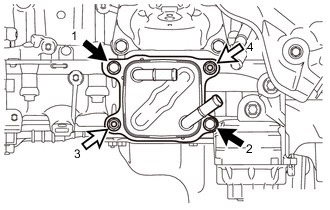

Bolt 
Nut Tighten the 2 nuts and 2 bolts in the order shown in the illustration.
- Torque:
- 25 N*m { 255 kgf*cm, 18 ft.*lbf }
-
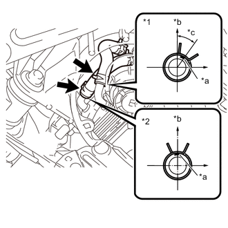
*1 No. 7 Water By-pass Hose *2 No. 8 Water By-pass Hose *a Paint Mark *b Upper Side *c 35° Install the No. 8 water by-pass hose to the oil cooler assembly with the hose clamp.
Note
-
Install the hose clamp so that it is positioned as shown in the illustration.
-
Install the No. 8 water by-pass hose so that the paint mark is positioned as shown in the illustration.
-
-
Install the No. 7 water by-pass hose to the oil cooler assembly with the hose clamp.
Note
-
Install the hose clamp so that it is positioned as shown in the illustration.
-
Align the paint mark on the oil cooler assembly pipe with the paint mark on the No. 7 water by-pass hose and the center of the hose clamp claw.
-
-
-
CONNECT NO. 5 INVERTER COOLING HOSE (for RHD)
-
Connect the No. 5 inverter cooling hose clamp to the front No. 1 stabilizer bracket LH.
-
-
CONNECT WIRE HARNESS (for RHD)
-
Connect the ground wire to the bracket with the bolt.
- Torque:
- 8.0 N*m { 82 kgf*cm, 71 in.*lbf }
-
Connect the 2 wire harness clamps.
-
-
INSTALL POWER STEERING LINK ASSEMBLY (for LHD)
-
ADD ENGINE OIL
-
ADD ENGINE COOLANT (for Engine)
-
INSTALL NO. 2 INVERTER COOLING HOSE (for LHD)
-
Install the No. 2 inverter cooling hose with the 2 hose clamps.
-
ADD coolant (for Inverter).
-
Inspect for coolant leak (for Inverter).
-
-
CHECK ENGINE OIL LEVEL
-
INSPECT FOR OIL LEAK
-
INSPECT FOR COOLANT LEAK (for Engine)
-
INSTALL NO. 2 ENGINE UNDER COVER (w/ No. 2 Engine Under Cover)
-
INSTALL FRONT SUSPENSION MEMBER BRACE
-
INSTALL REAR ENGINE UNDER COVER LH
-
INSTALL ENGINE UNDER COVER