OIL PUMP INSTALLATION
PROCEDURE
-
INSTALL TIMING CHAIN COVER ASSEMBLY
-
Remove any old packing (FIPG material) and be careful not to drop any oil on the contact surfaces of the timing chain cover assembly, camshaft housing sub-assembly, stiffening crankcase assembly, cylinder block sub-assembly and cylinder head sub-assembly.
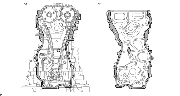
*a Engine Side *b Timing Chain Cover Assembly Side 
Clean and degrease - - Note
Be sure to clean and degrease the contact surfaces, especially the surfaces indicated in the illustration.
-
Apply a light coat of engine oil to a new oil pump gasket and a new oil pipe gasket.
-
Install the oil pump gasket to the stiffening crankcase assembly.
-
Install the oil pipe gasket to the oil strainer sub-assembly.
-
Install a water outlet gasket to the cylinder head sub-assembly.
-
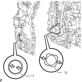
*1 Oil Pump Drive Rotor Spline *2 Crankshaft Timing Sprocket Align the oil pump drive rotor spline and crankshaft timing sprocket as shown in the illustration.
-
Apply seal packing as shown in the illustration.
Seal packing Toyota Genuine Seal Packing Black, Three Bond 1207B or equivalent. 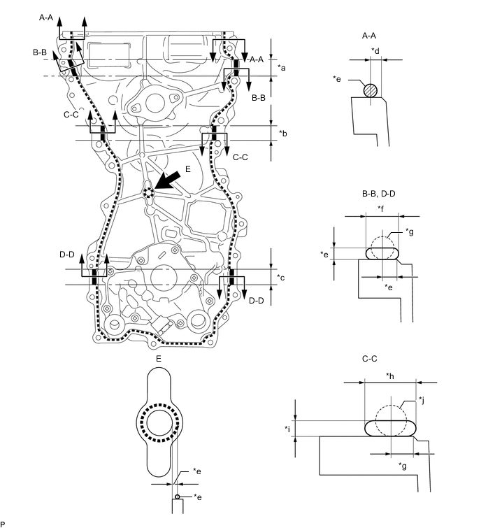
*a 28 mm (1.102 in.) *b 25 mm (0.984 in.) *c 26 mm (1.024 in.) *d 2.5 mm (0.0984 in.) *e 3.0 mm (0.118 in.) *f 7.0 mm (0.276 in.) or more *g 5.0 mm (0.197 in.) *h 13 mm (0.512 in.) or more *i 3.0 mm (0.118 in.) or more *j 7.0 mm (0.276 in.) Application Specification Area Seal Packing Diameter Seal Packing Width Seal Packing Height Application Position from Inside Seal Line Dashed line area 3.0 mm (0.118 in.) - - 2.5 mm (0.0984 in.) A - A 3.0 mm (0.118 in.) - - 2.5 mm (0.0984 in.) B - B 5.0 mm (0.197 in.) 7.0 mm (0.276 in.) or more 3.0 mm (0.118 in.) or more 3.0 mm (0.118 in.) C - C 7.0 mm (0.276 in.) 13 mm (0.512 in.) or more 3.0 mm (0.118 in.) or more 5.0 mm (0.197 in.) D - D 5.0 mm (0.197 in.) 7.0 mm (0.276 in.) or more 3.0 mm (0.118 in.) or more 3.0 mm (0.118 in.) E 3.0 mm (0.118 in.) - - 3.0 mm (0.118 in.) Note
-
Install the timing chain cover assembly within 3 minutes and tighten the bolts and nuts within 10 minutes after applying seal packing.
-
Do not add engine oil within 2 hours of installation.
-
Do not start the engine for at least 2 hours after the installation.
-
-
Temporarily install the timing chain cover assembly with the 19 bolts (A, B and C) and 2 nuts.
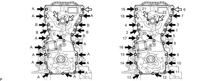

Bolt 
Nut Standard Bolt Item Length Bolt Diameter Bolt A 30 mm (1.18 in.) 8.0 mm (0.315 in.) Bolt B 35 mm (1.38 in.) 10 mm (0.394 in.) Bolt C 45 mm (1.77 in.) 8.0 mm (0.315 in.) Note
Make sure that there is no oil on the threads of the bolt B .
-
Tighten the 19 bolts and 3 nuts in the order shown in the illustration.
- Torque:
- Bolt A, C and Nut
- 21 N*m { 214 kgf*cm, 15 ft.*lbf }
- Bolt B
- 55 N*m { 561 kgf*cm, 41 ft.*lbf }
-
-
INSTALL TIMING GEAR CASE OR TIMING CHAIN CASE OIL SEAL
-
INSTALL WATER OUTLET SUB-ASSEMBLY
-
Install a new O-ring to the timing chain cover assembly.
-
Install the water outlet sub-assembly with the 2 bolts and nut.
- Torque:
- 10 N*m { 102 kgf*cm, 7 ft.*lbf }
-
-
INSTALL NO. 11 WATER BY-PASS HOSE
-
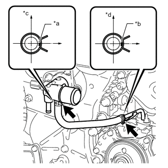
*a Paint Mark (White) *b Paint Mark (Yellow) *c Rear Side *d Upper Side Install the No. 11 water by-pass hose with the 2 hose clamps.
Note
-
Install the hose clamp so that it is positioned as shown in the illustration.
-
Install the No. 11 water by-pass hose so that the white paint mark and yellow paint mark are positioned as shown in the illustration.
-
-
-
INSTALL NO. 13 WATER BY-PASS HOSE
-
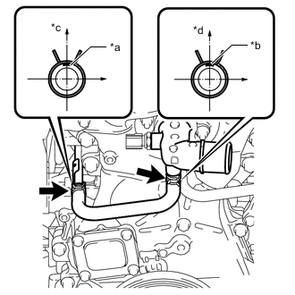
*a Paint Mark (Yellow) *b Paint Mark (White) *c Upper Side *d Engine Front Side Install the No. 13 water by-pass hose with the 2 hose clamps.
Note
-
Install the hose clamp so that it is positioned as shown in the illustration
-
Install the No. 13 water by-pass hose so that the white paint mark and yellow paint mark are positioned as shown in the illustration.
-
-
-
INSTALL CRANKSHAFT PULLEY ASSEMBLY
-
INSTALL CRANKSHAFT POSITION SENSOR
-
INSTALL OIL LEVEL DIPSTICK GUIDE
-
INSTALL OIL LEVEL DIPSTICK SUB-ASSEMBLY
-
INSTALL CYLINDER HEAD COVER SUB-ASSEMBLY
-
Apply a light coat of engine oil to 3 new camshaft bearing cap oil hole gaskets.
-
Install the 3 camshaft bearing cap oil hole gaskets to the camshaft bearing caps.
-
Install a new cylinder head cover gasket to the cylinder head cover sub-assembly.
-
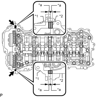
*1 Timing Chain Cover Assembly *2 Camshaft Housing Sub-assembly *a 5.0 mm (0.197 in.) Seal Packing Apply seal packing as shown in the illustration.
Seal packing Toyota Genuine Seal Packing Black, Three Bond 1207B or equivalent. Standard seal diameter 3.0 to 6.0 mm (0.118 to 0.236 in.) Note
-
Be sure to clean and degrease the contact surfaces.
-
Install the cylinder head cover sub-assembly within 3 minutes and tighten the bolts within 15 minutes after applying seal packing.
-
Do not add engine oil within 2 hours of installation.
-
Do not start the engine for at least 2 hours after the installation.
-
-
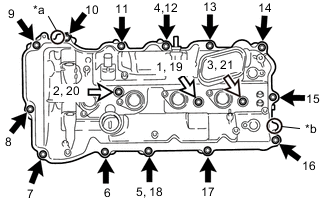
*a Pin A *b Pin B Bolt A Bolt B Align the pin holes in the cylinder head cover sub-assembly with the pin A and pin B in this order, and then install the cylinder head cover sub-assembly.
-
Temporarily install 3 new seal washers and the 3 bolts B.
-
Temporarily install the 13 bolts A.
-
Tighten the 16 bolts in the order shown in the illustration.
- Torque:
- 12 N*m { 122 kgf*cm, 9 ft.*lbf }
Standard Bolt Item Length Bolt A 25 mm (0.984 in.) Bolt B 35 mm (1.38 in.)
-
-
INSTALL IGNITION COIL ASSEMBLY
-
INSTALL WIRING HARNESS CLAMP BRACKET
-
Install the 2 wiring harness clamp brackets to the timing chain cover assembly with the 2 bolts.
- Torque:
- 10 N*m { 102 kgf*cm, 7 ft.*lbf }
-
-
CONNECT ENGINE WIRE
-
Connect the wire harness clamp.
-
Connect the 2 ground wires to the timing chain cover assembly with the 2 bolts.
- Torque:
- 10 N*m { 102 kgf*cm, 7 ft.*lbf }
-
Install the wire harness clamp bracket to the timing chain cover assembly with the bolt.
- Torque:
- 10 N*m { 102 kgf*cm, 7 ft.*lbf }
-
Install the wire harness clamp bracket to the timing chain cover assembly with the 2 bolts.
- Torque:
- 10 N*m { 102 kgf*cm, 7 ft.*lbf }
-
Connect the connector to the engine coolant temperature sensor.
-
Connect the 4 wire harness clamps.
-
Install the wire harness clamp bracket to the cylinder head cover sub-assembly with the bolt.
- Torque:
- 10 N*m { 102 kgf*cm, 7 ft.*lbf }
-
Connect the 2 wire harness clamps to the wire harness clamp bracket.
-
Connect the engine wire with the 5 nuts.
- Torque:
- 10 N*m { 102 kgf*cm, 7 ft.*lbf }
-
Connect the connector to the engine oil pressure switch.
-
Connect the 4 connectors to the 4 ignition coil assemblies.
-
Connect the 2 connectors to the 2 VVT sensors.
-
Connect the 2 connectors to the 2 camshaft timing oil control valve assemblies.
-
Connect the 3 wire harness clamps.
-
-
CONNECT VENTILATION HOSE ASSEMBLY
-
Connect the ventilation hose assembly to the ventilation valve sub-assembly with the clip.
-
-
CONNECT OIL COOLER TUBE SUB-ASSEMBLY
-
Connect the oil cooler tube sub-assembly with the 2 bolts.
- Torque:
- 22 N*m { 224 kgf*cm, 16 ft.*lbf }
-
Connect the engine ground wire clamp to the oil cooler tube sub-assembly.
-
-
CONNECT NO. 1 HV WATER PUMP OUTLET PIPE
-
Connect the No. 1 HV water pump outlet pipe with the 2 bolts.
- Torque:
- 22 N*m { 224 kgf*cm, 16 ft.*lbf }
-
-
INSTALL FUEL PUMP WITH SEAL SUB-ASSEMBLY
-
CHECK ENGINE OIL LEVEL
-
INSPECT FOR ENGINE OIL LEAK
-
INSTALL NO. 2 ENGINE UNDER COVER (w/ No. 2 Engine Under Cover)
-
INSTALL FRONT SUSPENSION MEMBER BRACE
-
INSTALL ENGINE UNDER COVER