INTAKE MANIFOLD INSTALLATION
PROCEDURE
-
INSTALL STUD BOLT
Tech Tips
If a stud bolt is deformed or the threads are damaged, replace it.
-
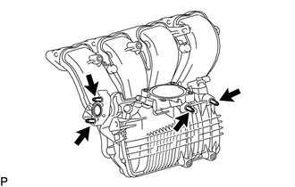
Using an E6 "TORX" socket wrench, install the 4 stud bolts to the intake manifold.
- Torque:
- 4.0 N*m { 41 kgf*cm, 35 in.*lbf }
-
-
INSTALL INTAKE MANIFOLD
-
Install a new gasket to the intake manifold.
-
Temporarily install the intake manifold and intake manifold stay with the 7 bolts.
Tech Tips
If an intake manifold stay is deformed or damaged, replace it.
-
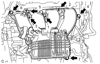
Tighten the 7 bolts in the order shown in the illustration.
- Torque:
- 28 N*m { 286 kgf*cm, 21 ft.*lbf }
-
Connect the No. 2 water by-pass hose to the intake manifold clamp.
-
Install the 2 wire harness clamp brackets to the intake manifold with the 3 bolts.
- Torque:
- 10 N*m { 102 kgf*cm, 7 ft.*lbf }
-
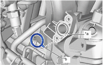
*a Groove *b Protrusion w/o EGR system:
-
Install a new EGR inlet gasket to the intake manifold.
Tech Tips
Align the protrusion of the EGR inlet gasket with the groove of the intake manifold.
-
Install the EGR hole cover plate to the intake manifold with the 2 nuts.
- Torque:
- 10 N*m { 102 kgf*cm, 7 ft.*lbf }
-
-
Connect the 7 wire harness clamps to the intake manifold and 2 wire harness clamp brackets.
-
Connect the ventilation hose assembly to the intake manifold and slide the clip to secure it.
-
Connect the ventilation hose assembly to the wire harness clamp bracket.
-
Connect the No. 2 fuel vapor feed hose to the intake manifold.
-
Connect the No. 1 fuel pipe clamp to the wire harness clamp bracket.
-
-
INSTALL NO. 2 EGR PIPE (w/ EGR System)
-
CONNECT INLET HEATER WATER HOSE A
-
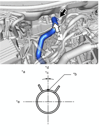
*a View A *b Marking *c Clip Installation Angle (-15 to 15°) *d Upper Side *e RH Side Connect the inlet heater water hose A to the radiator unit sub-assembly and slide the clip to secure it.
Note
-
Engage the clip within the area shown in the illustration.
-
Do not apply excessive force to the inlet heater water hose A.
-
-
-
INSTALL OUTLET HEATER WATER HOSE A
-
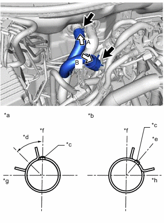
*a View A *b View B *c Marking *d Clip Installation Angle (30 to 60°) *e Clip Installation Position *f Upper Side *g RH Side *h Front Side Install the outlet heater water hose A to the radiator unit sub-assembly and No. 2 water by-pass pipe and slide the 2 clips to secure it.
Note
-
Engage the clip within the area shown in the illustration.
-
Do not apply excessive force to the outlet heater water hose A.
-
-
Install the heater water hose set to the outlet heater water hose A.
-
-
INSTALL PURGE VALVE (PURGE VSV)
-
INSTALL VACUUM SENSOR ASSEMBLY
-
INSTALL INJECTOR DRIVER
-
CONNECT INVERTER RESERVE TANK ASSEMBLY
-
Connect the inverter reserve tank assembly to the No. 1 inverter reserve tank bracket with the 2 bolts.
- Torque:
- 12.5 N*m { 127 kgf*cm, 9 ft.*lbf }
-
-
INSTALL THROTTLE BODY WITH MOTOR ASSEMBLY
-
INSTALL INLET NO. 1 AIR CLEANER
-
INSTALL COOL AIR INTAKE DUCT SEAL