PROCEDURE
- Click here
INSTALL THROTTLE BODY GASKET
-
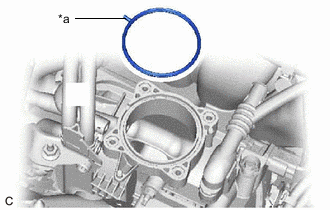
*a Protrusion Install a new throttle body gasket onto the intake manifold with the protrusion of the throttle body gasket oriented as shown in the illustration.
-
- Click here
INSTALL THROTTLE BODY WITH MOTOR ASSEMBLY
-
Install the throttle body with motor assembly to the intake manifold with the 4 bolts.
10 N*m 102 kgf*cm 7 ft.*lbf -
Connect the No. 2 water by-pass hose and No. 3 water by-pass hose to the throttle body with motor assembly and slide the 2 clips to secure them.
-
Connect the throttle body with motor assembly connector.
-
- Click here
INSTALL AIR CLEANER HOSE ASSEMBLY
-
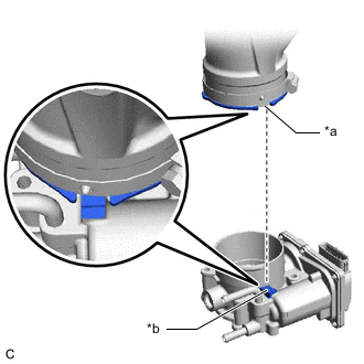
*a Cutout *b Protrusion Align the cutout of the air cleaner hose assembly with the protrusion of the throttle body with motor assembly, and install the air cleaner hose assembly.
-
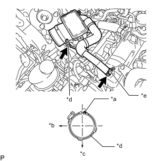
*a Protrusion *b Front *c Left *d Hose Clamp *e Clip Tighten the hose clamp to the position shown in the illustration.
4.0 N*m 41 kgf*cm 35 in.*lbf Note:Fit the protrusion on the air cleaner hose assembly into the hole of the hose clamp.
Tip:Make sure the direction of the clip is as shown in the illustration.
-
Connect the ventilation hose to the throttle body with motor assembly and slide the clip to secure it.
-
- Click here
INSTALL AIR CLEANER CAP WITH NO. 2 AIR CLEANER HOSE
-
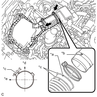
*a Groove *b Matchmark *c Stopper *d Top *e Right Connect the air cleaner cap with No. 2 air cleaner hose to the air cleaner hose assembly.
Tip:Make sure the direction of the installation is as shown in the illustration.
-
Install the air cleaner cap with No. 2 air cleaner hose with the 4 clamps.
-
Tighten the hose clamp to the position shown in the illustration.
4.0 N*m 41 kgf*cm 35 in.*lbf -
Connect the wire harness clamp to the air cleaner cap with No. 2 air cleaner hose.
-
Connect the mass air flow meter sub-assembly connector.
-
- Click here
ADD ENGINE COOLANT
- Click here
INSPECT FOR ENGINE COOLANT LEAK
- Click here
INSTALL NO. 1 ENGINE COVER SUB-ASSEMBLY
- Click here
PERFORM INITIALIZATION
Note:Be sure to perform this procedure after removing and reinstalling the throttle body with motor assembly.
-
Connect the GTS to the DLC3.
-
Clear the DTCs.
-
w/ EGR System:
-
w/o EGR System:
-
-
Turn the power switch on (IG) without operating the accelerator pedal.
Note:If the accelerator pedal is operated, perform the above steps again.
-
Perform "Inspection After Repair".
-
w/ EGR System:
-
w/o EGR System:
-
-
Put the engine in inspection mode (maintenance mode).
-
Start the engine and check that the MIL is not illuminated. After the engine is warmed up, check that the idle speed is within the specified range with the A/C switch off.
Standard 950 to 1050 rpm Note:
-
Be sure to perform this step with all accessories off.
-
Make sure that the shift lever is in P.
-
-
Perform a road test and confirm that there are no abnormalities.
-